Japan 2025
Prefectures visited: Fukuoka, Kumamoto, Oita
Prefectures visited: Fukuoka, Kumamoto, Oita
Niigata & Sado Island
We visited 3 prefectures:
Komagane, a small town in Nagano prefecture.
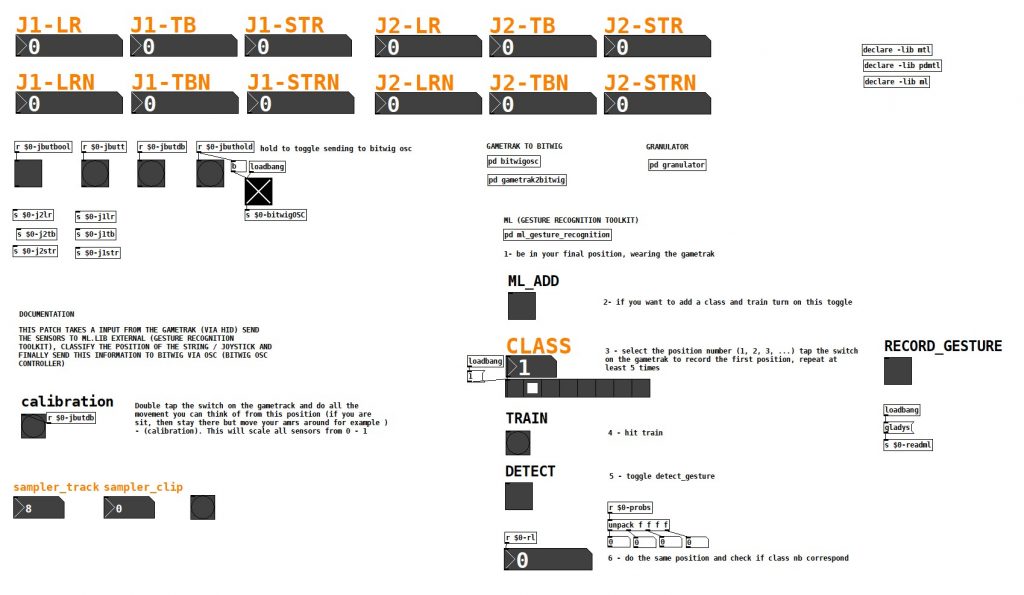
This patch takes an input from the Gametrak (via HID), sends the sensor data to the ml.lib external (Gesture Recognition Toolkit), classifies the position of the string/joystick, and finally sends this information to Bitwig via OSC (Bitwig OSC controller).
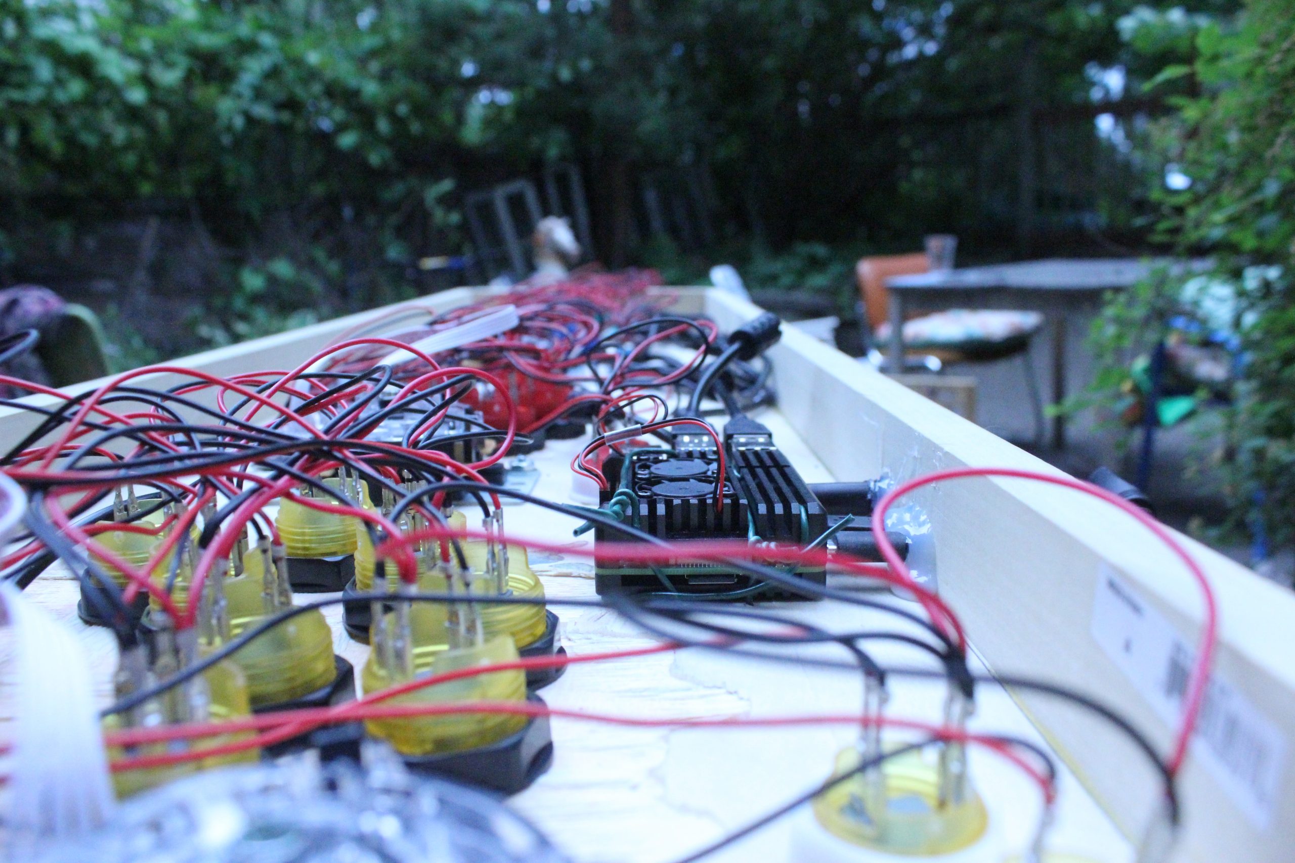
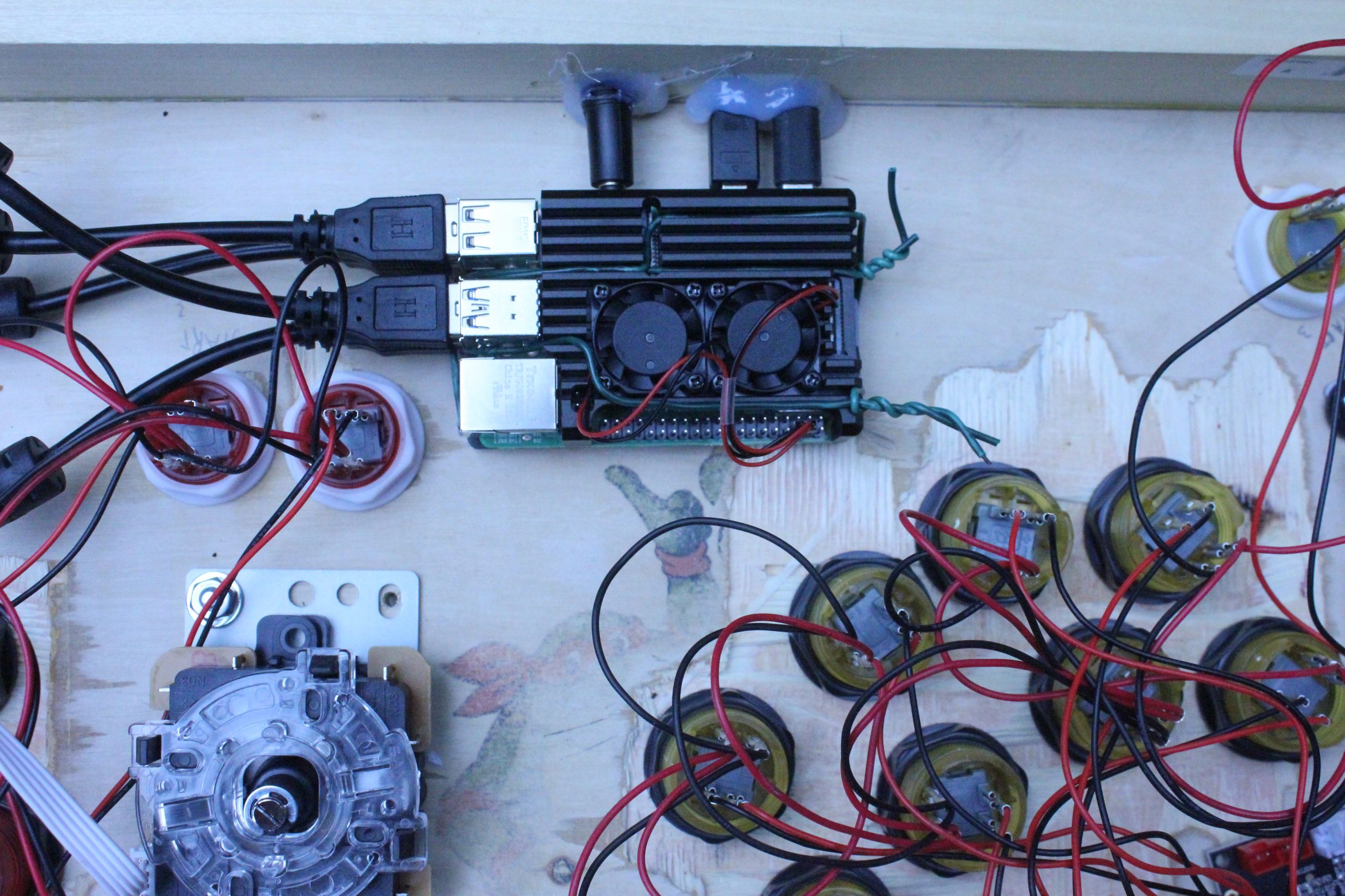
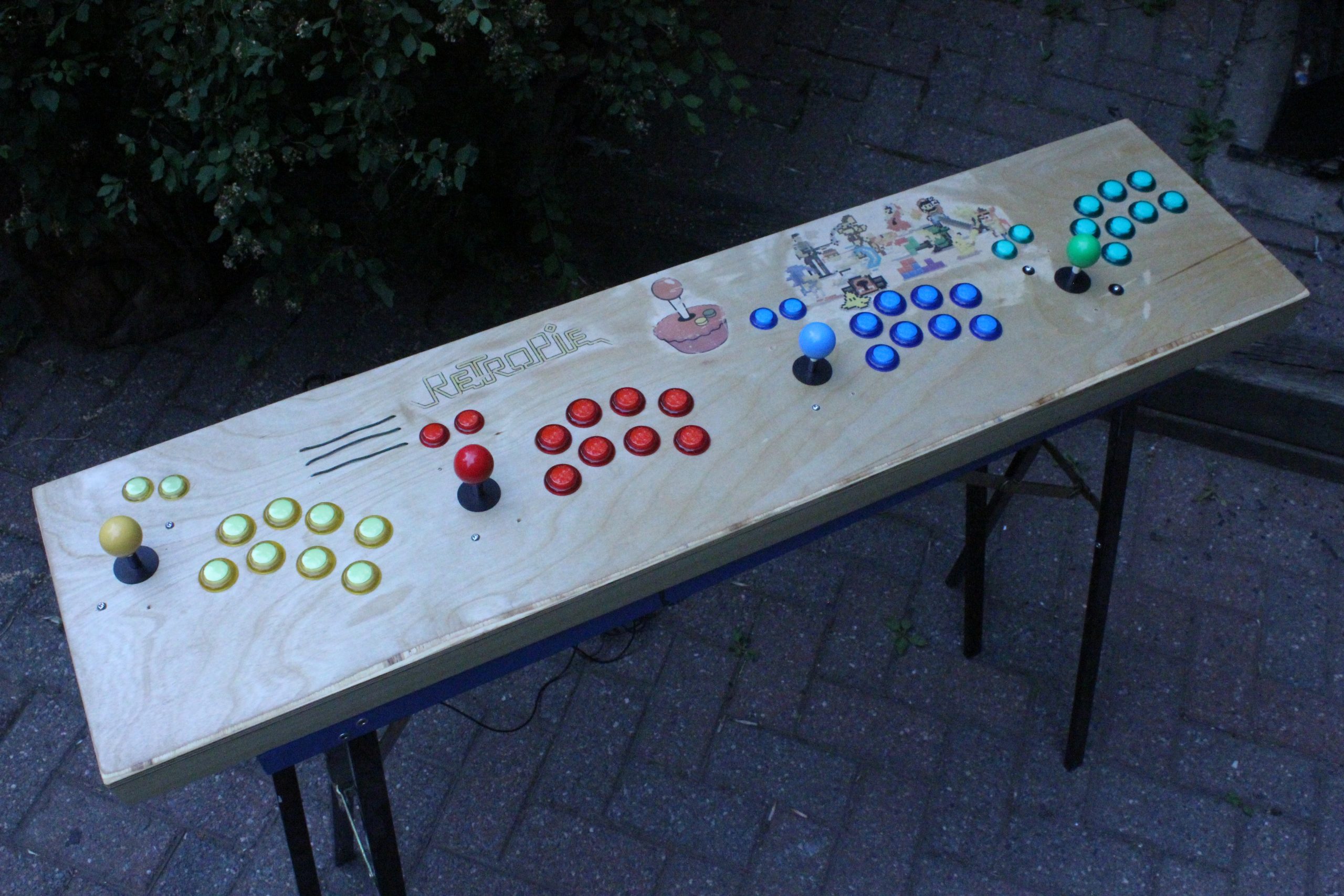
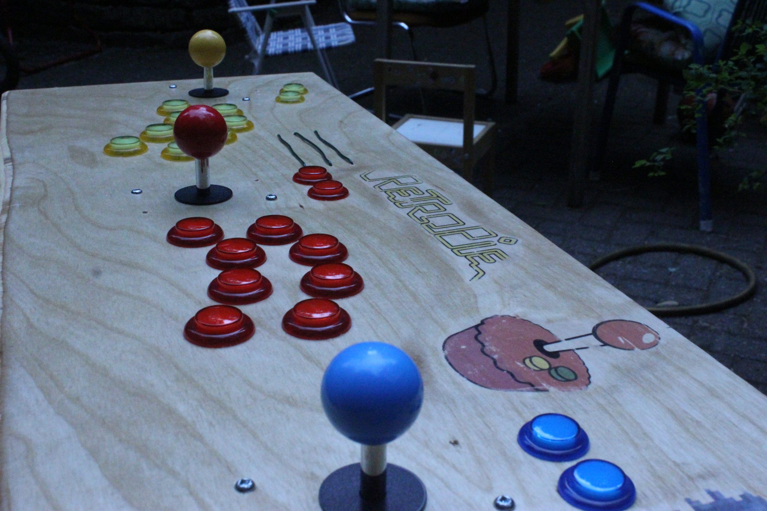
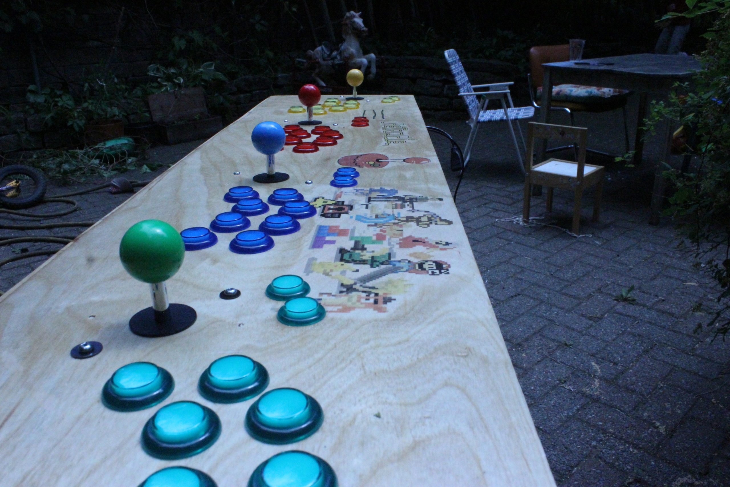
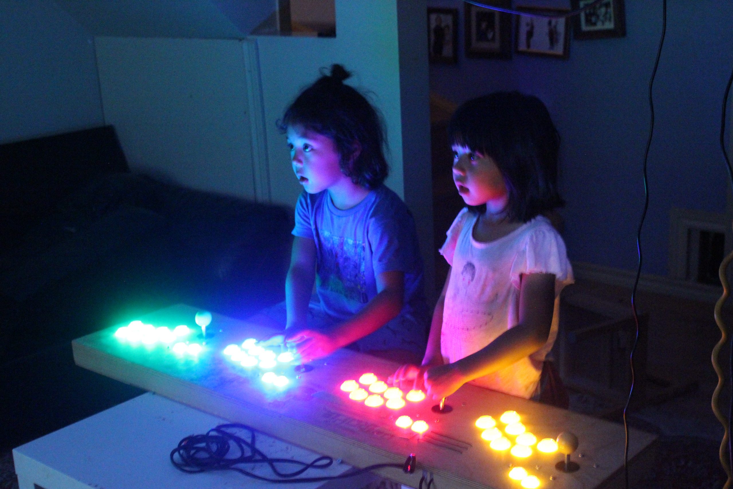
When I was young, I had to go to an arcade center, use my 25 cents for 45 seconds of fun. I think I am getting nostalgic, I bought a 4 players joystick & buttons arcade kit, hook it up to a RPI 4 and seach the web for arcadepunks. Bingo! As a bonus, it’s also serving as our media center (Kodi is installed).
Just a quick video of the phibow connected to the phimatics project (not yet documented).
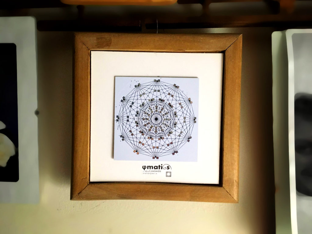
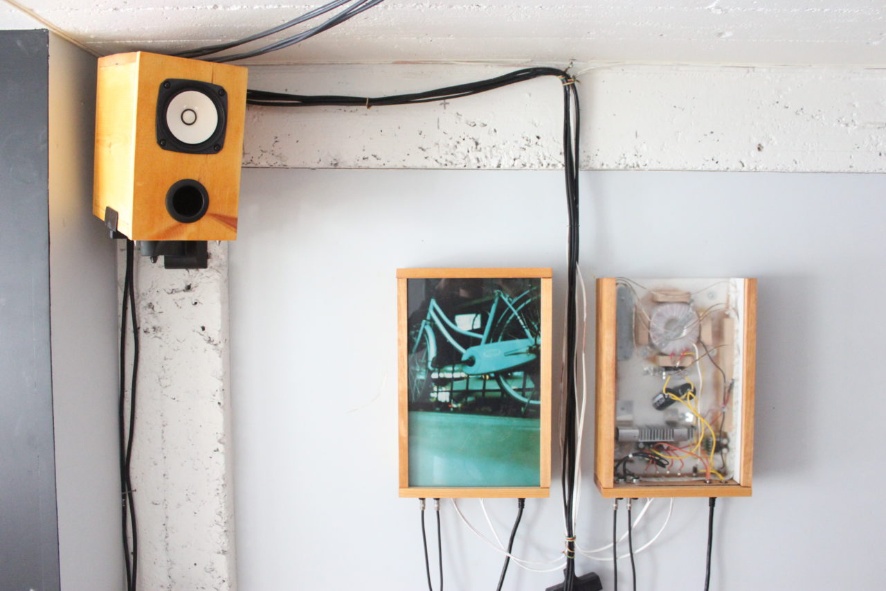
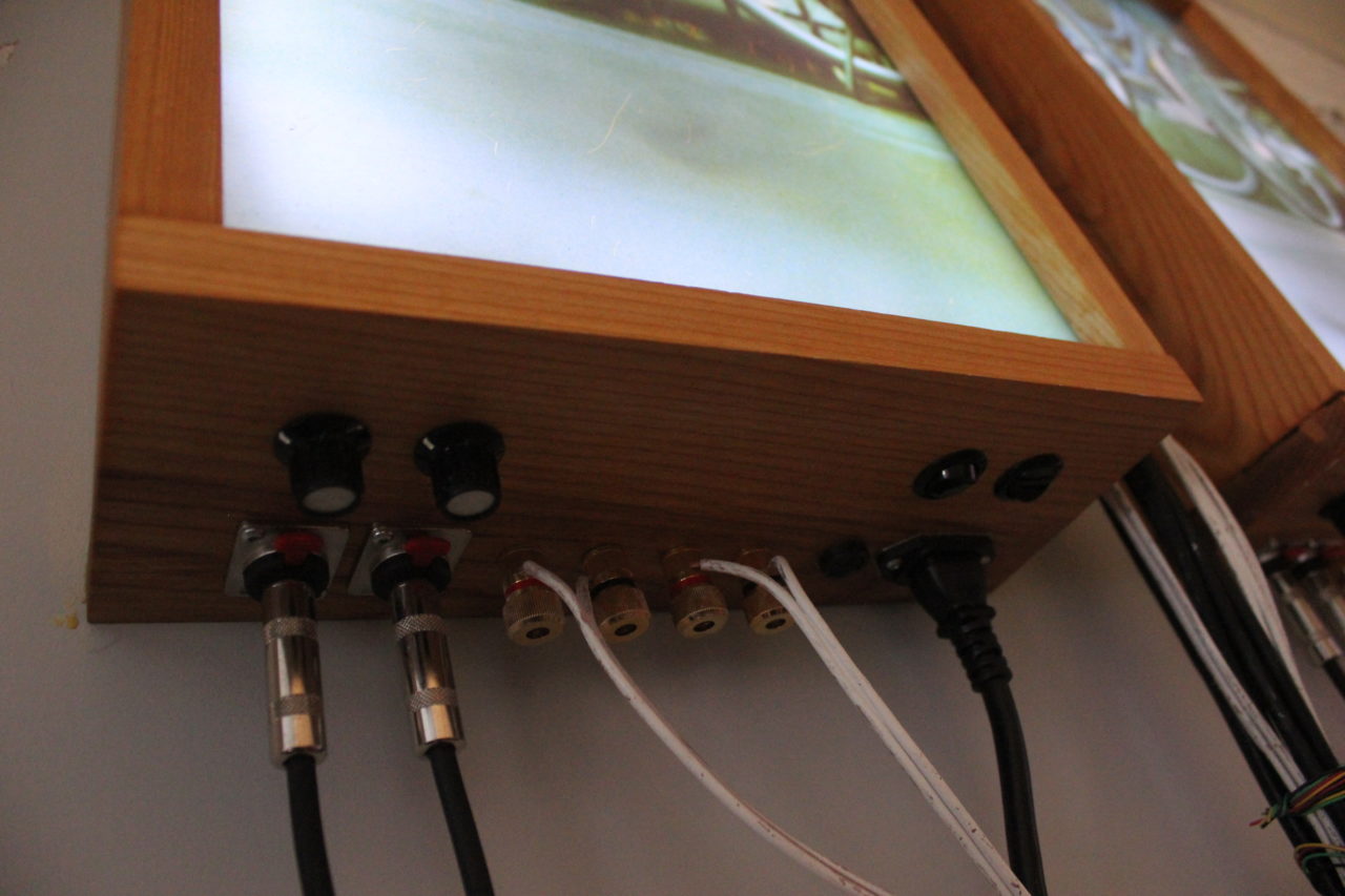
Thanks to Ouellet Fredericks family for exposing (nice frame) my PCB in their home!
Had an old bass laying around, lots of love & hot glue later the bassynth was born. Will document a little bit later (including the electronic drum), just wanted to share what my friend confettis created:
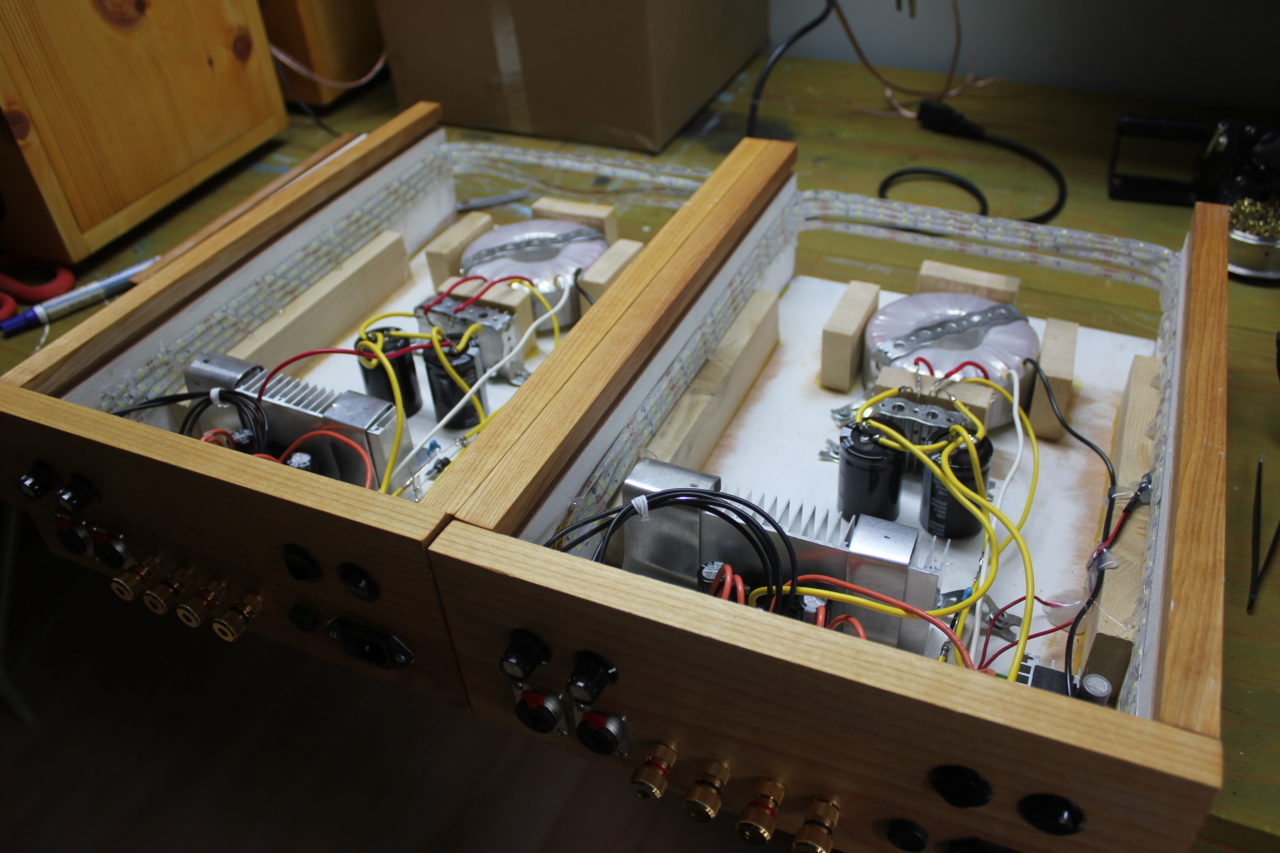
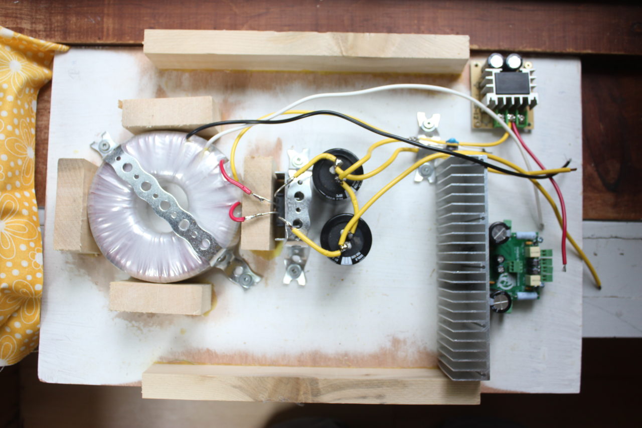
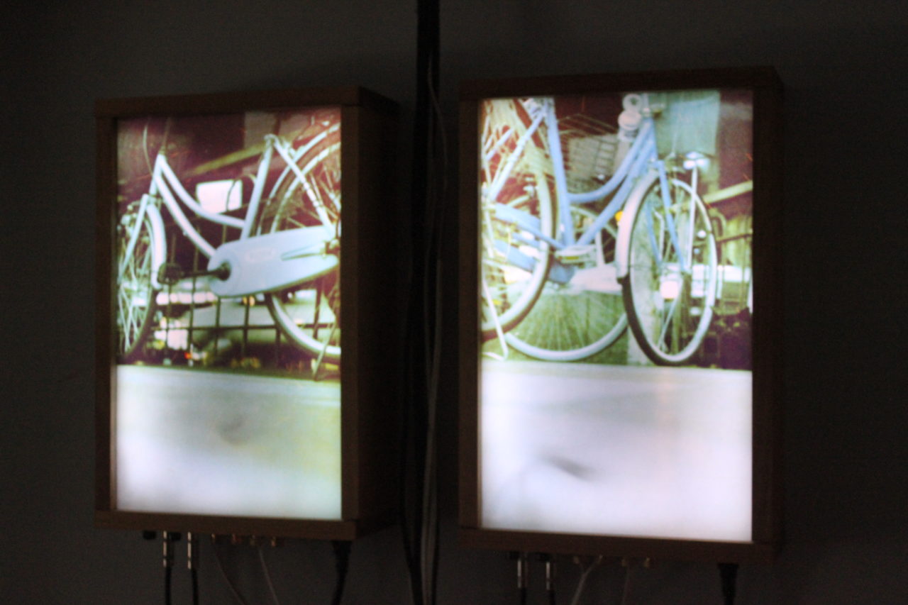
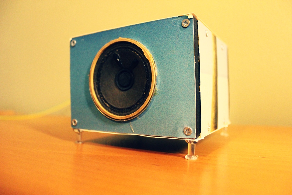
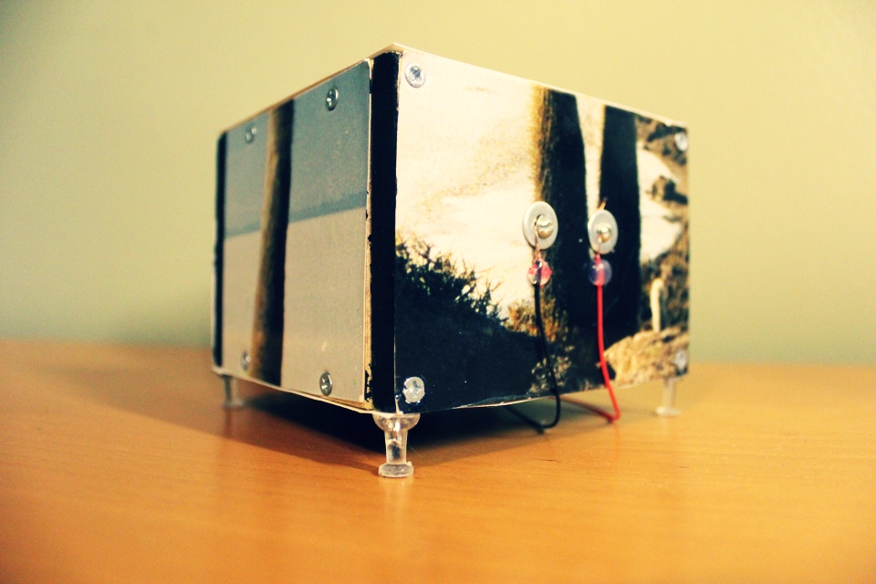
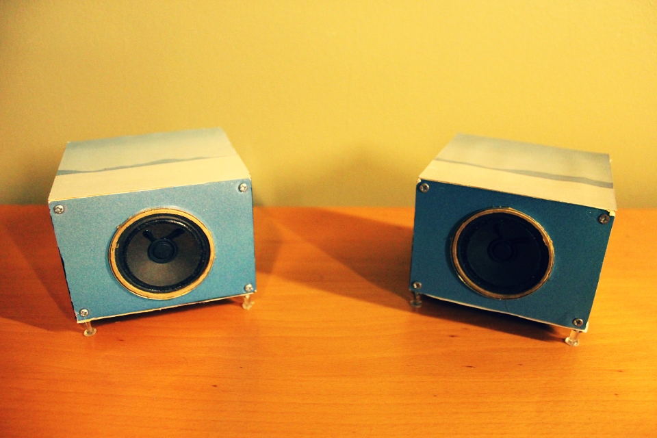
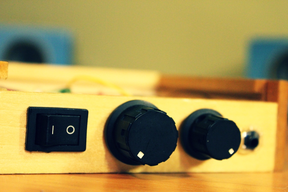
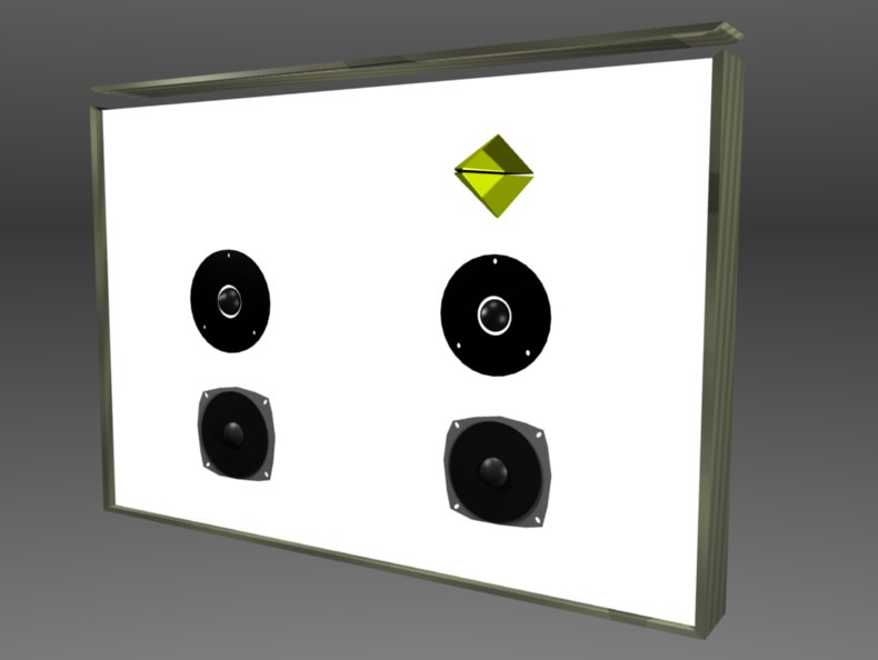
The title says it all. Same pcb from the phiamp project, just added a light box x2 == quadraphonic party. Speakers are full-range. Using HoaLibrary (High Order Ambisonics for Pure Data) as a spatializer (don’t forget to invert phase of speaker if they point at each other).
La Boîte à oiseaux is a combination of 3 projects:
It’s a media center built in an amplified box with speech recognition capabilities. La boîte can understand as many languages as Kiku offers (currently English, Japanese, German & Portuguese) and since Kiku works offline, there’s no need to be connected to the internet.
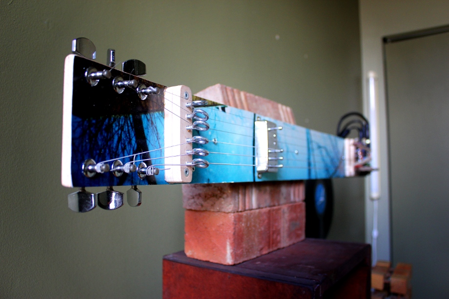
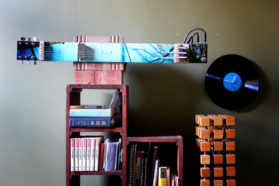
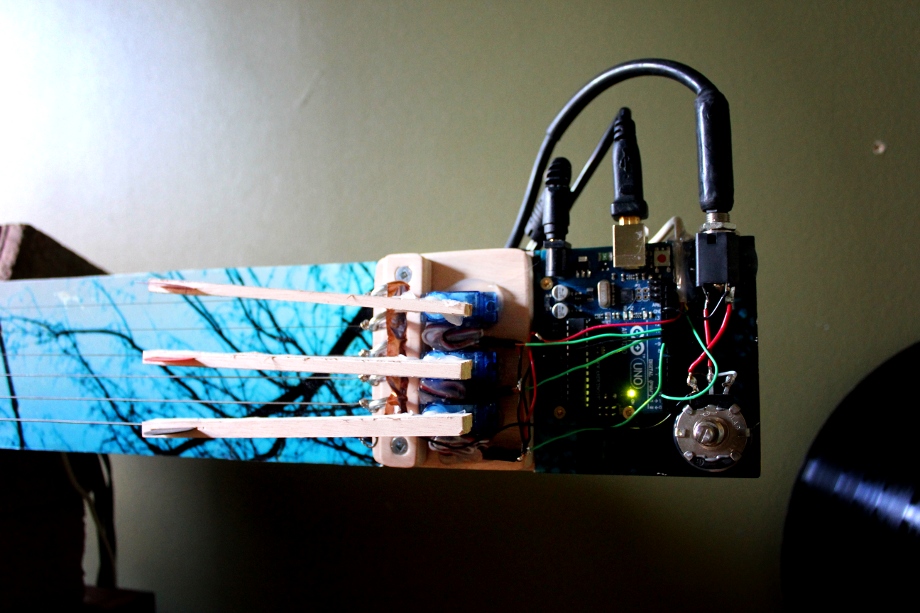
a custom built actuated guitar controlled by pure data. 3 micro servo are strumming the strings and pure data take care of the global pitch shifting. the humbucker is really far from the bridge to avoid getting noise from the magnetic field (there’s still some). included is a relay to turn on high voltage stuff (a light, a disco ball and whatnot).
i think i made this project to showcase puredata fx capabilities, for this i had to make it controllable from the internet (streaming webcam / audio on pdpatchrepo). finally there’s a chatbot (alice) / tts when only one person is connected to the stream.
i don’t think it is useful without the actuated guitar, but here’s the patch:
http://pdpatchrepo.info/patches/patch/40
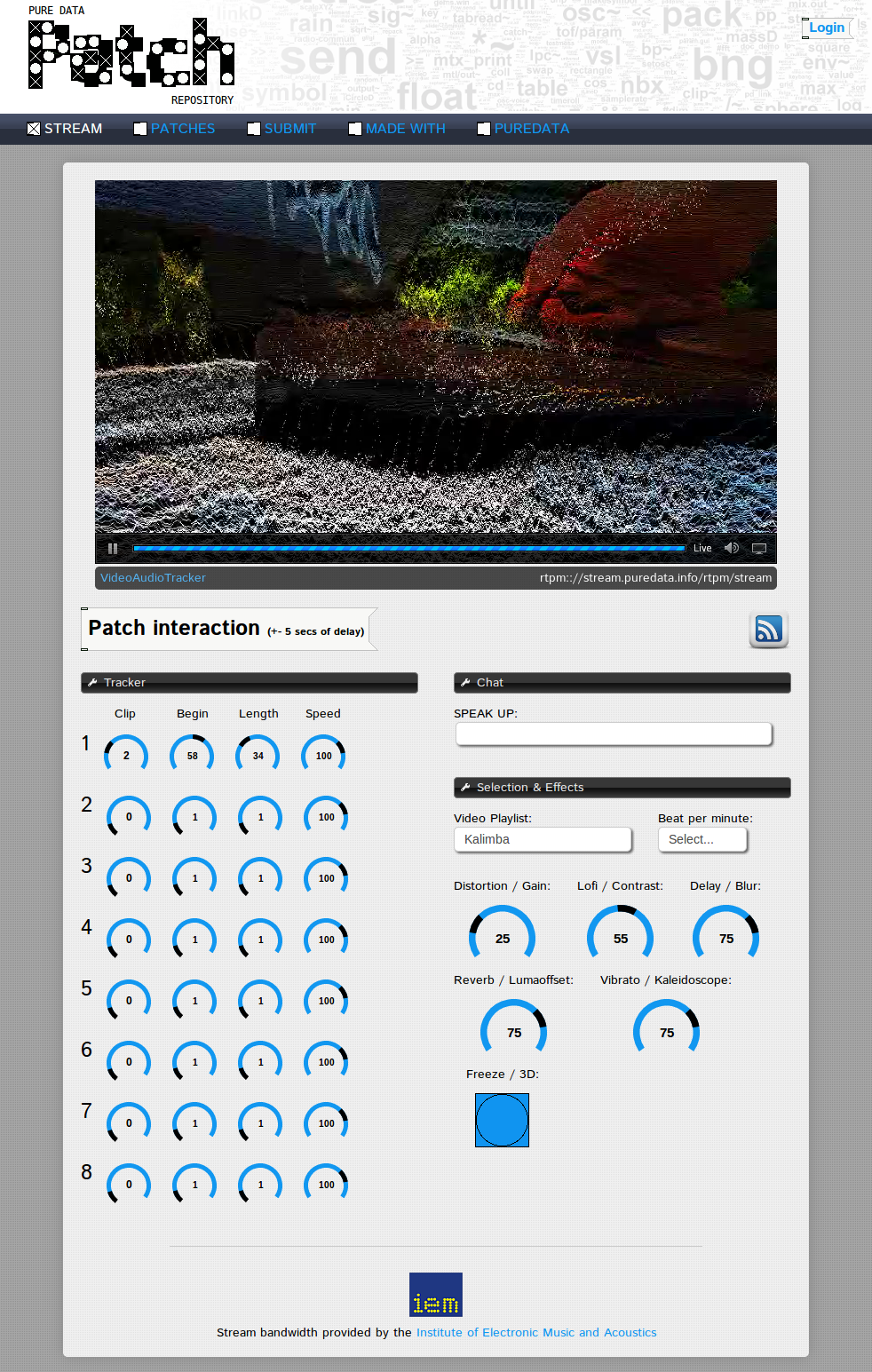
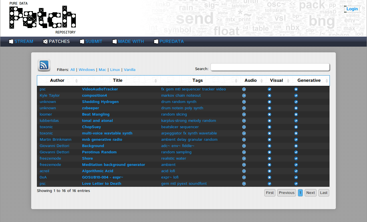
Pure Data have a repository for abstractions and externals, but not for patches. Not anymore, I took the time to code one. There’s multiple ways of searching a patch: by platforms, tags (adc~, notein), is audio, is video, is generative…
The site also feature a live stream (video & audio) with networked gui so that multiple visitors can interact with the streaming patch. Of course there’s a latency in the feed when playing with the knobs (betweeen 3-5 seconds) but it is still a fun way to jam with others. The bandwidth is provided by the Institute of Electronic Music and Acoustics.
Patch (when a new patch is added)
Stream (when a new patch is stream)
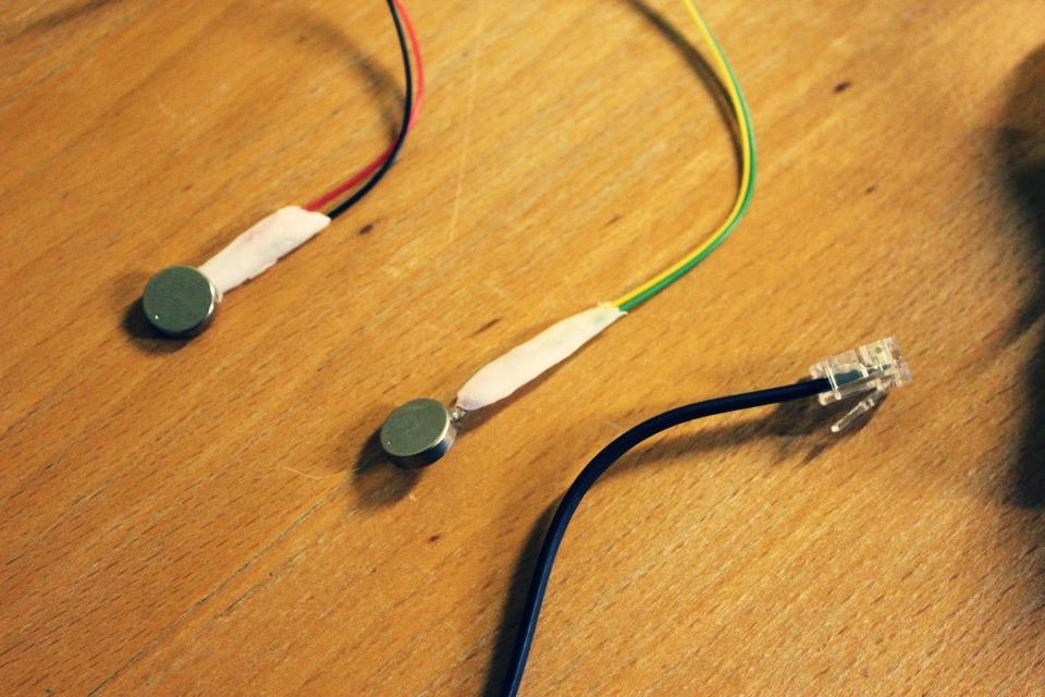
a usb powered amplifier featuring 2 vibrators and 4 leds sync with music.
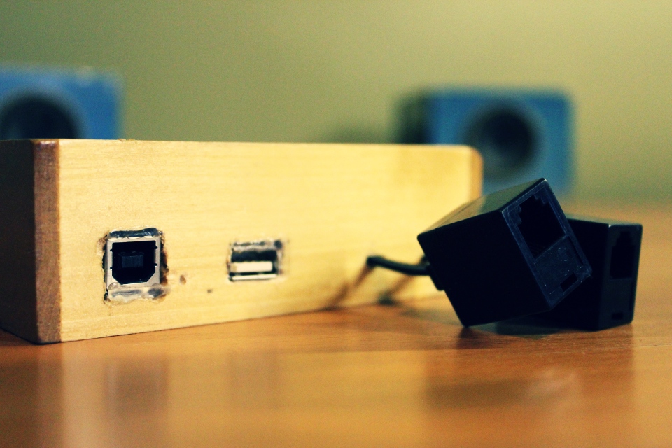
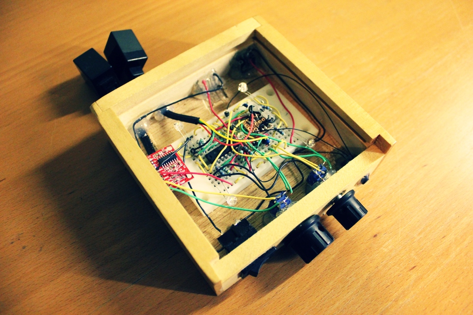
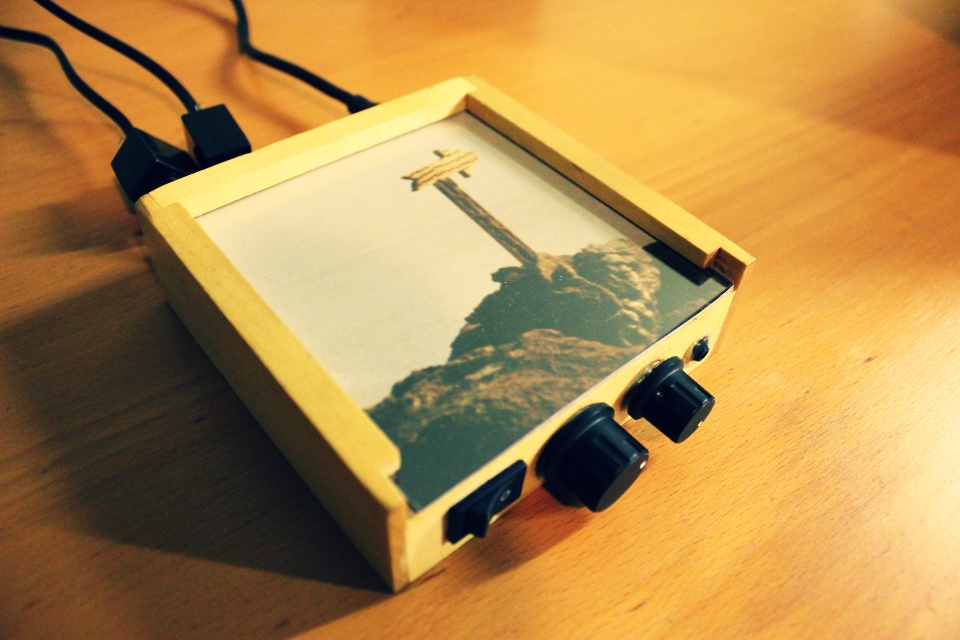

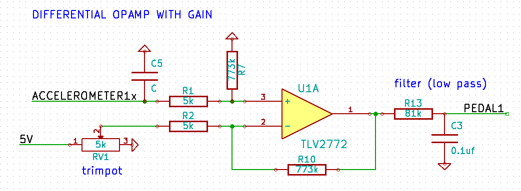
it is possible to build an expressive pedal using the 3-axis MMA7361 accelerometer (you can buy this on ebay for 3$ CAD). we are dealing with a limited angle (1110mv to 1300mv) so the output of the x-axis needs to be subtracted and amplified: differential amplifier & op-amp voltage and gain calculator. the next step is to convert the analog signal to digital (using the ADC from your microcontroller) and finally interpret that in pure data (in my case). there’s a hardware low-pass filter but i am also using infinite impulse response low-pass filter in puredata (iir). feel free to write me directly if you need help reproducing this setup.
4 years ago i built an expressive pedal using a led and a photo-resistor:
there is also this solution using capacitance sensor and v-usb:
http://www.ise.pw.edu.pl/~wzab/MIDI/pedal/index.html
of course, the traditional potentiometer solution:
http://philaudio.wordpress.com/projects/phi-t/phi-t-control/
so i needed to get in shape (still do): borrowed an exercise bike from a friend. i wanted to see the biggest cities in the world while doing so: google earth. all that was missing was a way to control google earth from the bike: kinect and the speech recognition sdk.
my solution is a modification of this project: Kinect Excercise. added speech recognition (let me ride… a big city) and some keyboard shortcut and mouse automation for google earth (using http://www.autoitscript.com) + OSC for an upcoming project (small game based on this concept). you can download the hacky c# project.
i finally found something useful to do with my kinect: tracking the neck of a guitar and using gesture recognition to control the FX rack of a pure data patch.
i used the natural interaction middleware hand tracking example (PointViewer) and added open sound control (liblo). latency is 33ms. you can download the source and the executable for linux (64bit).
i am using the neat gesture recognition toolkit by Nick Gillian. using the DTW (Dynamic Time Warping) example (coded in openframeworks), i simply added open sound control to send the predicted gesture to pure data. you can download the source and the executable for linux (64bit).
nothing fancy here, just a patch to send the tracking via osc to the gesture recognition i get back the result from it, apply some FX to an incoming signal using X, Y, Z. you can download the patch.
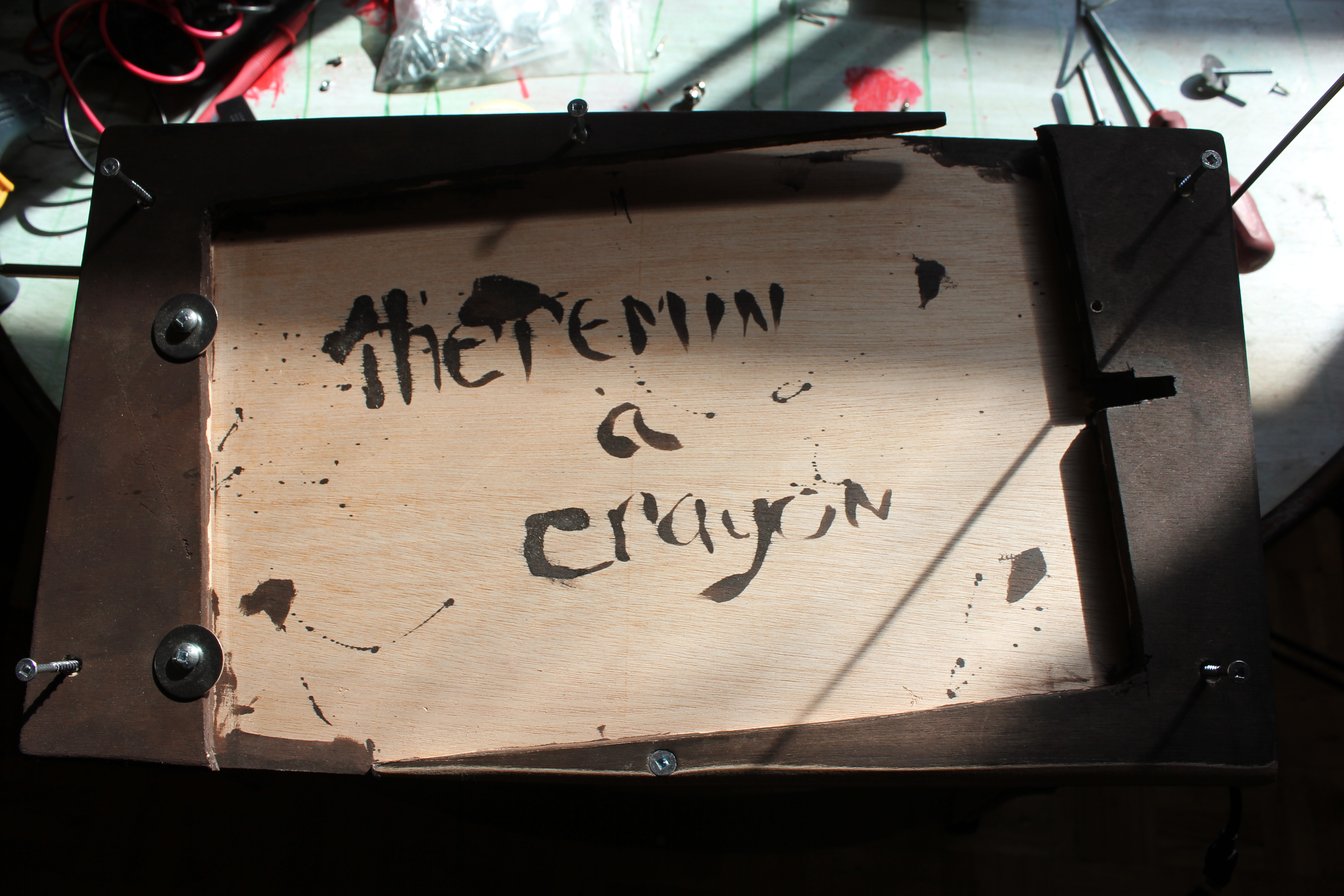
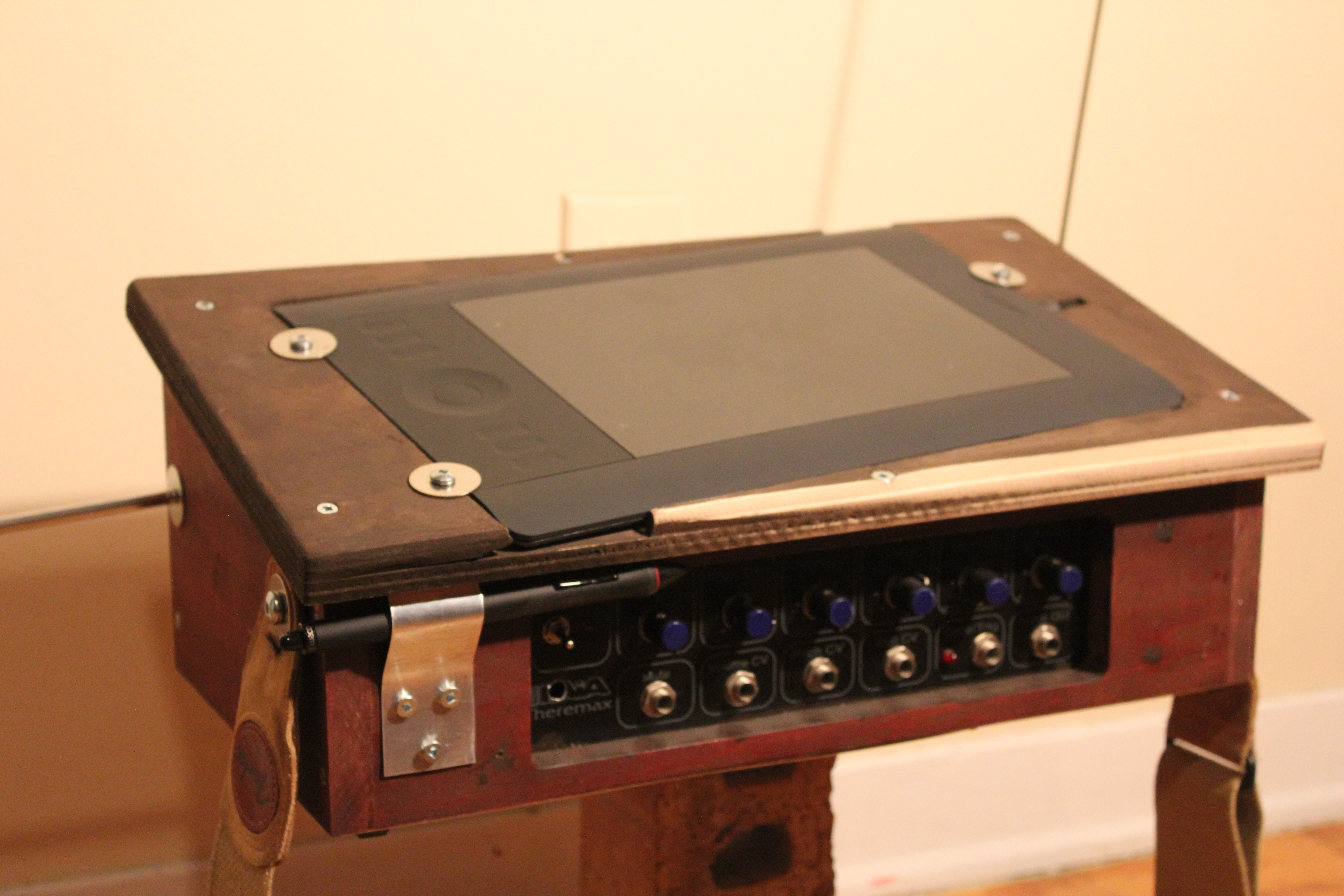
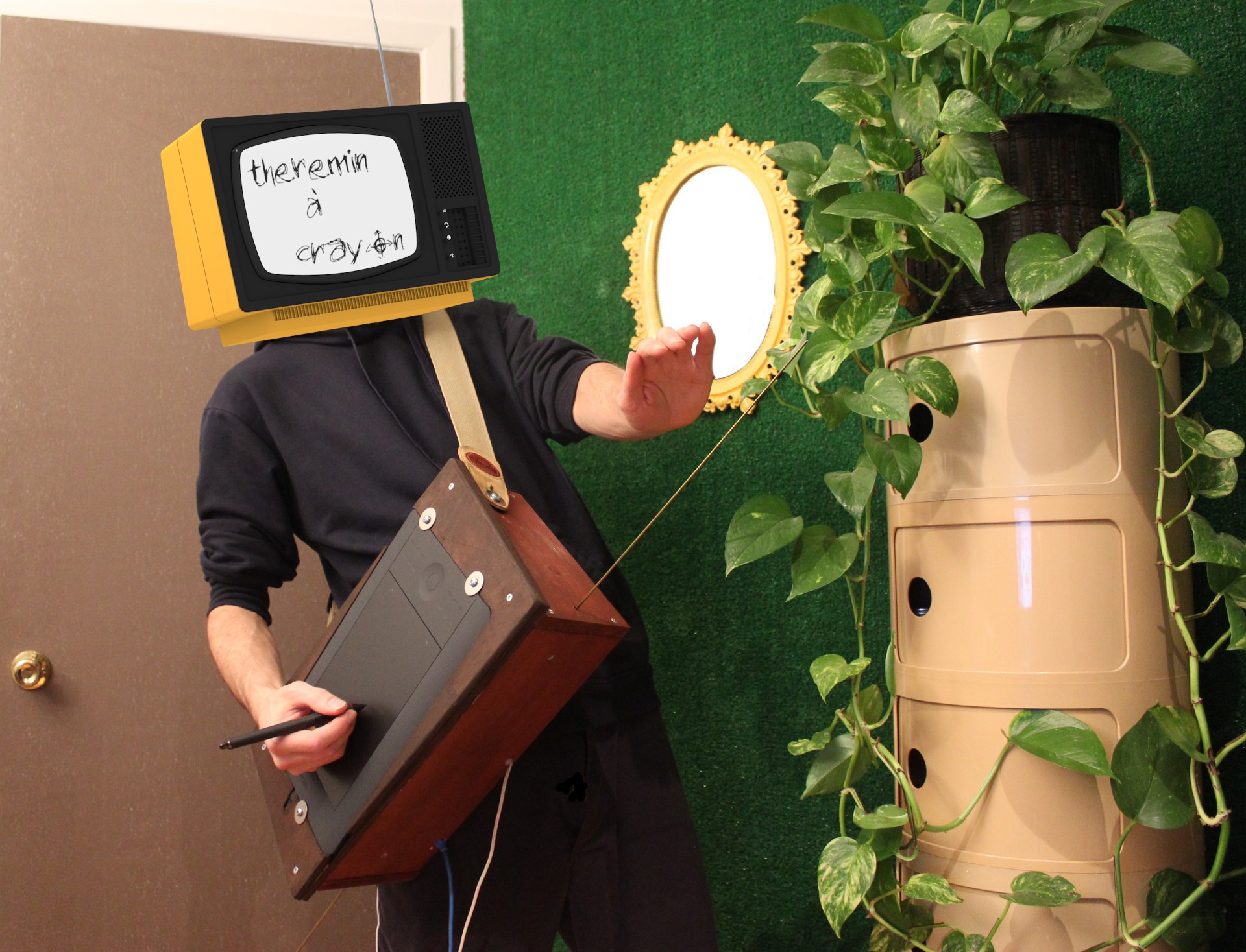
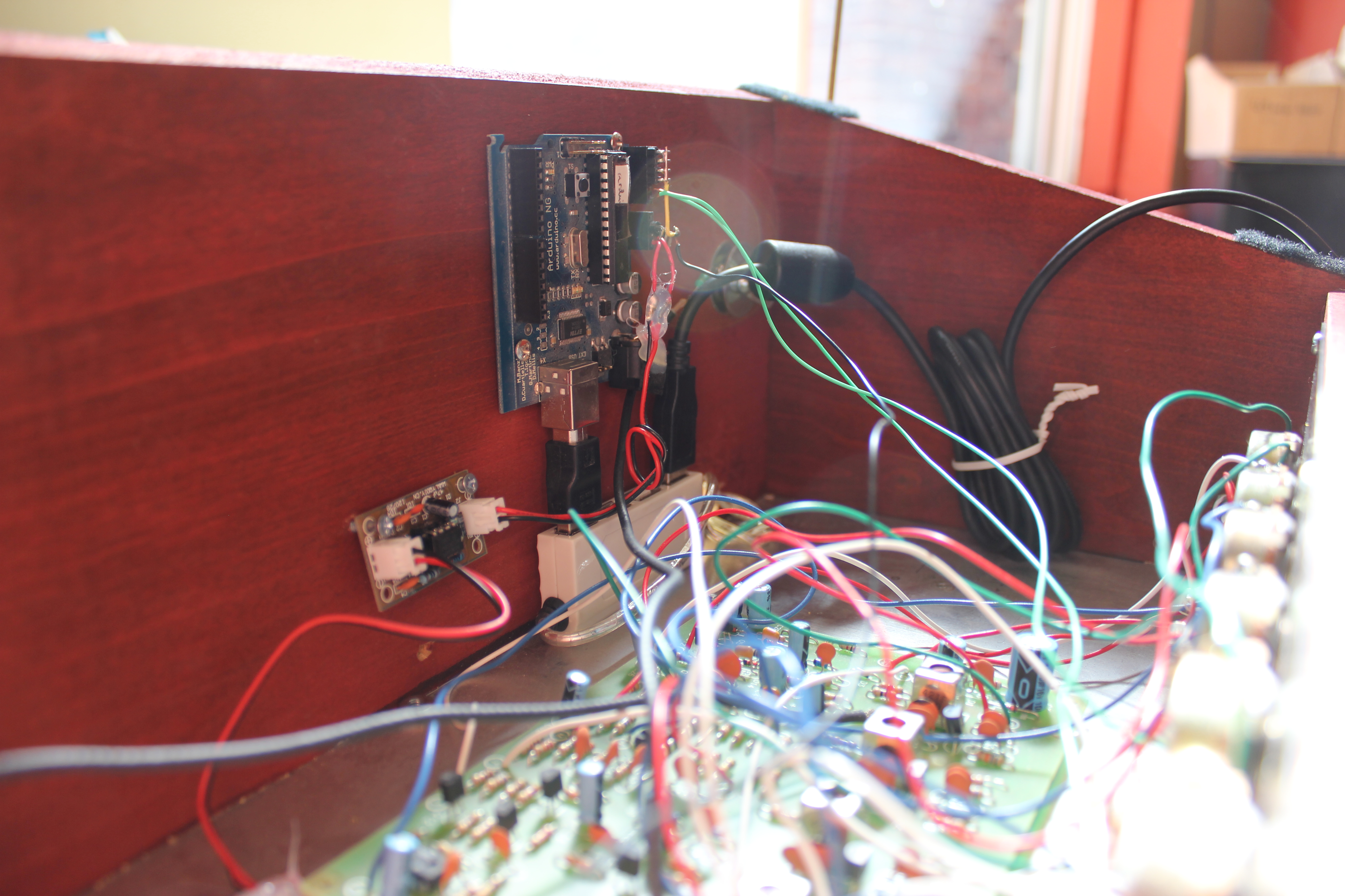

The “Not-just-for-sci-fi electronic instrument” that is played without being touched + a graphic tablet on top & some very simple electronics in the case (power / convert the theremin via USB). Both antennas (control voltage for volume and pitch) are routed to PureData.
The patch is really just a bridge (open sound control) to MyPaint (open-source graphics application for digital painters). Right now the volume is linked to the diameter of the brush and the pitch is linked to the brightness color (this can be changed in the code see below).
BTW this is the beauty of the open source movement: had the idea in the morning, talk to some people on #mypaint in the afternoon, hack the source for my needs during the night and went to bed with a working prototype. Ready-made Solutions Require Ready-made Problems; For Everything Else There Is Open Source Software!
MyPaint: share/gui/document.py -> pyliblo server (receive from pd)
import liblo, sys class Document (CanvasController): def __init__(self, app, leader=None): global created if(created == False): self.server = liblo.Server(9997) self.server.add_method("/mp/radius", 'f', self.oscradius) self.server.add_method("/mp/zoom", 'f', self.osczoom) self.server.add_method("/mp/rotate", 'f', self.oscrotate) gobject.timeout_add(20, self.pollcheck) created = True def oscradius(self, path, args): adj = self.app.brush_adjustment['radius_logarithmic'] adj.set_value(args[0]) def oscv(self, path, args): h, s, v = self.app.brush.get_color_hsv() v = args[0] if v < 0.005: v = 0.005 if v > 1.0: v = 1.0 self.app.brush.set_color_hsv((h, s, v)) def osczoom(self, path, args): self.tdw.set_zoom(args[0]) def oscrotate(self, path, args): self.tdw.set_rotation(args[0]) def pollcheck(self): self.server.recv(10) self.finished = False Stroke.serial_number += 1 self.serial_number = Stroke.serial_number return True |
MyPaint: share/mypaint/lib/stroke.py -> pyliblo client (send pressure, x, y to pd)
import liblo, sys def __init__(self): self.target = liblo.Address(1234) def record_event(self, dtime, x, y, pressure, xtilt,ytilt): self.tmp_event_list.append((dtime, x, y, pressure, xtilt,ytilt)) liblo.send(self.target, "/mypaint/pressure", pressure) |
PureData patch:
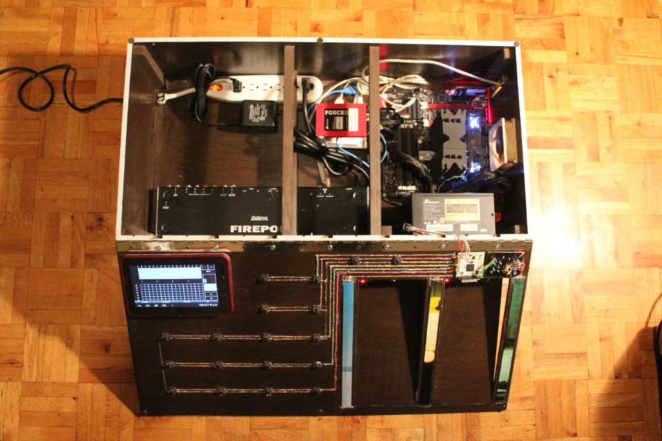
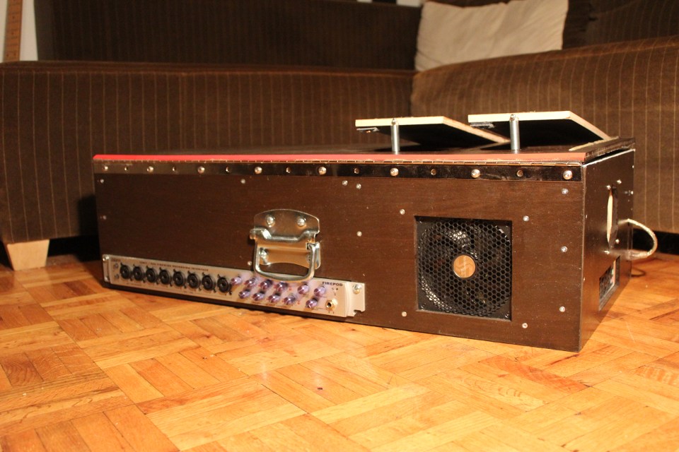
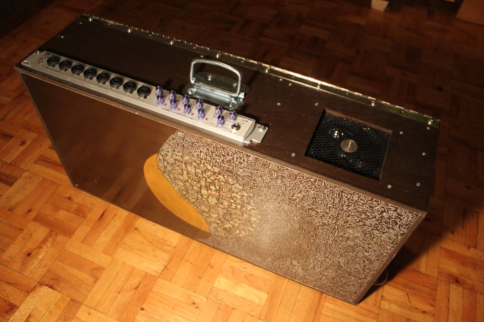
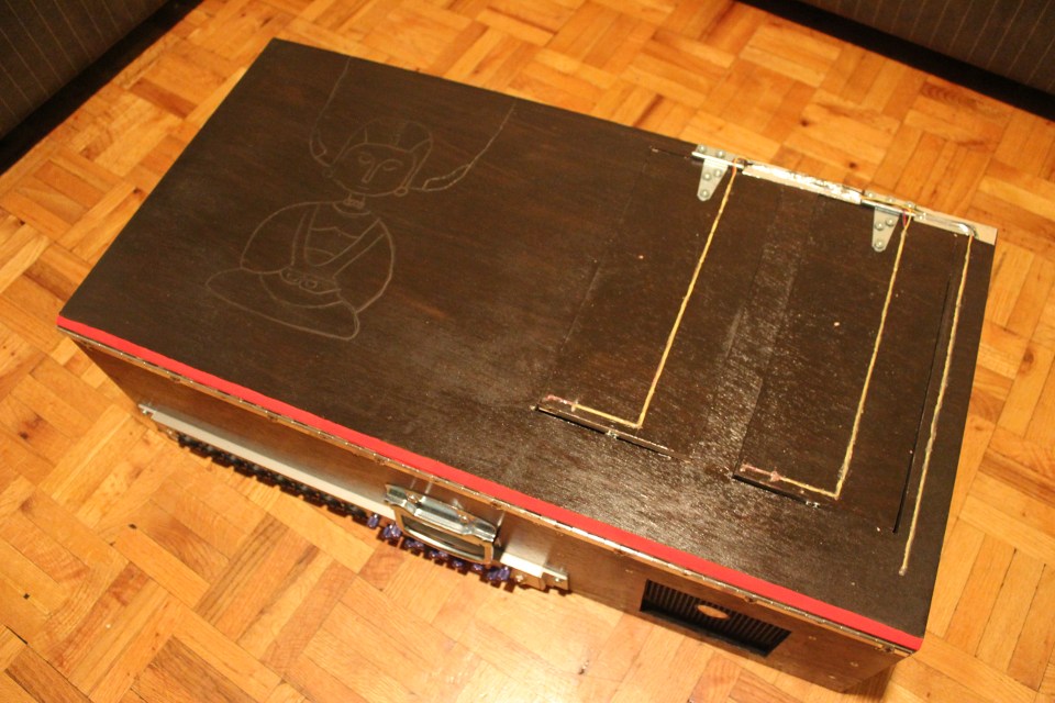
how heavy?
32lb (14.5 kg) roughly a medium-sized dog
what are you going to do with it?
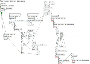
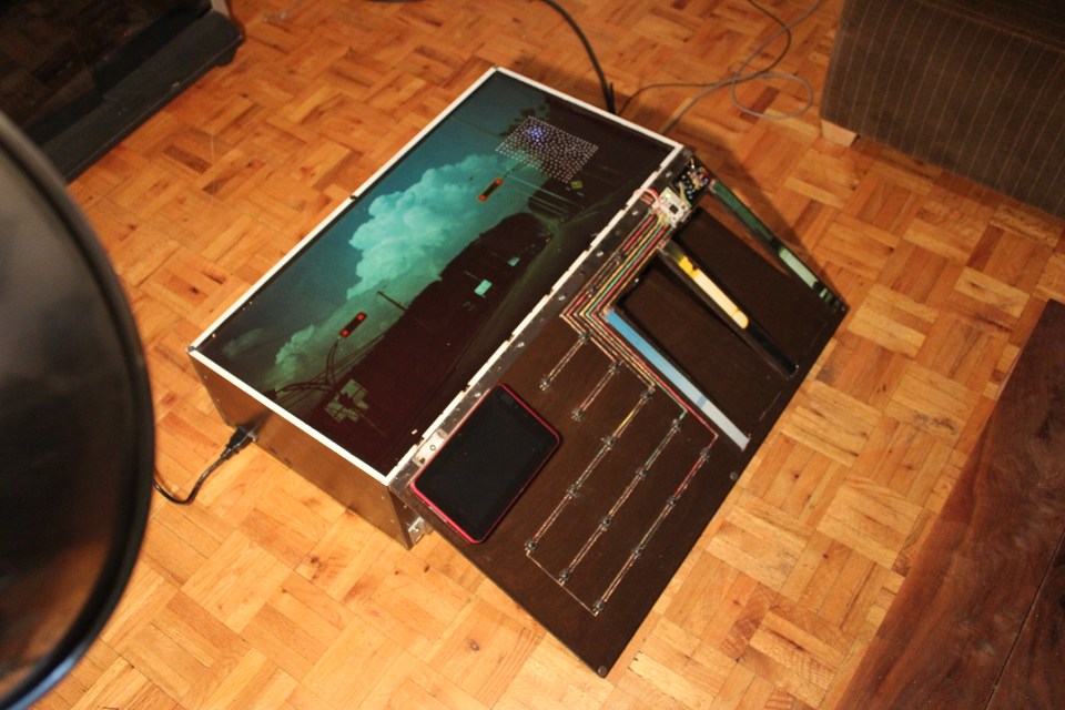
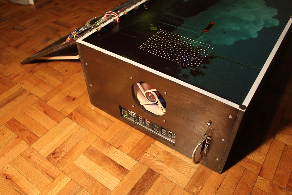
a centralized place for my digit/art project and my analog output. think of it as an effects unit or dsp in a box, but it’s also a silent computer with good processing power (as the time of this writing). the main project is to remix videos on the fly while playing an instrument.
what os/software are you using?
ubuntu studio with a low-latency kernel; pure data (effect rack, video player); sooperlooper (looping station); control (osc android application) all open source project
what kind of wood did you use?
okoumé (marine plywood). it’s a light wood and i was able to cut it with a x-acto!
i want more information
sure! source of the project (mainly related to the electronics) are here

I’m working on the integration of kiku (voice recognition to control your OS) to Vinux (Linux for the visually impaired). For now the feedback about kiku is great, but one thing people wants is a solution for dictation (that is, speech to text). kiku could be use for that task, but sadly there is no good (accurate) acoustic model available under GPL (Voxforge is a good start, but not there yet – please contribute).
So i came up with this online speech recognition for dictation solution to overcome this limitation. Speak in different languages, spell check, translate and text to speech all in one place. You’ll need Google Chrome and a microphone.
EDIT: it seems that it is not working anymore… is an alternative: https://www.google.com/intl/en/chrome/demos/speech.html
on march 11 my apartment in tokyo was shook by an earthquake of magnitude 9.0:
since i don’t have a mobile phone (i must be the only one in japan without a keitai) i wasn’t aware of the incoming earthquake and my software was useless (being alert 10 minutes after the earthquake):
by detecting the primary waves we know in how many seconds (depending on the epicenter location) an earthquake will occur. i don’t know if it’s possible to build a p waves monitoring device (anyone?), but for now i’m using a free software (windows & japanese only) that send me an alert (no hardware required).
connecting the software to a microcontroller was not that hard, but since i don’t want to boot in windows just for monitoring the p waves i had to hack little. grosso modo: virtual box (windows in linux) -> autoit (checking for a p waves popup) -> create file <- linux bash checking for new file -> send serial command to arduino -> physical feedback.
please make a donation to the japanese red cross society

the idea is simple:
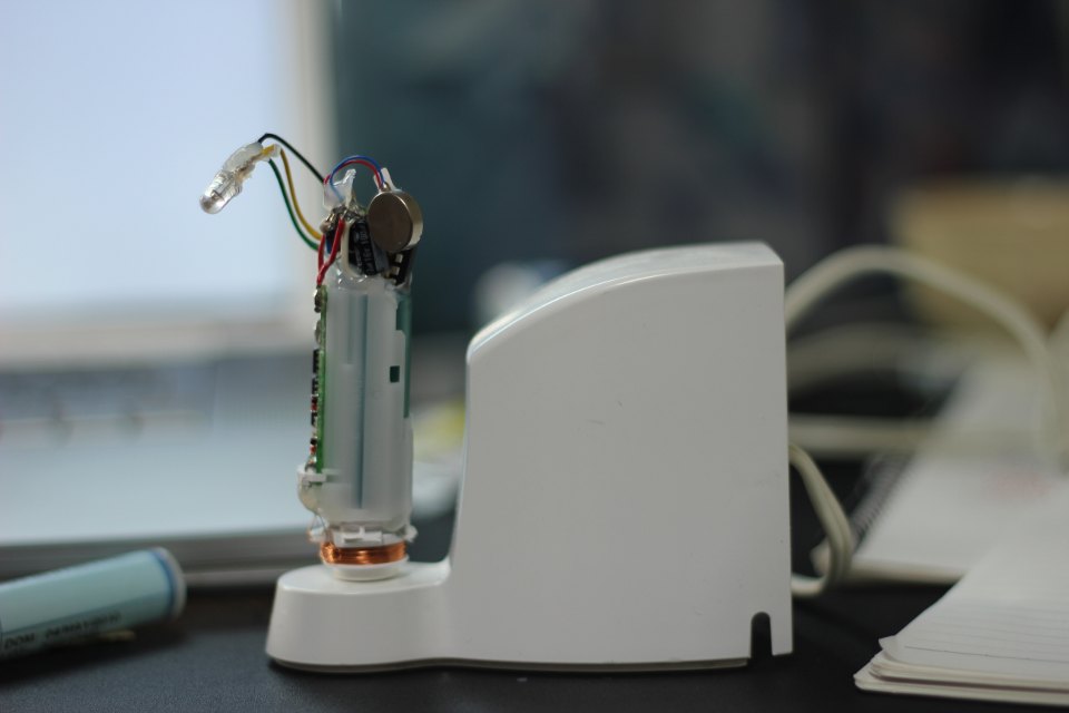
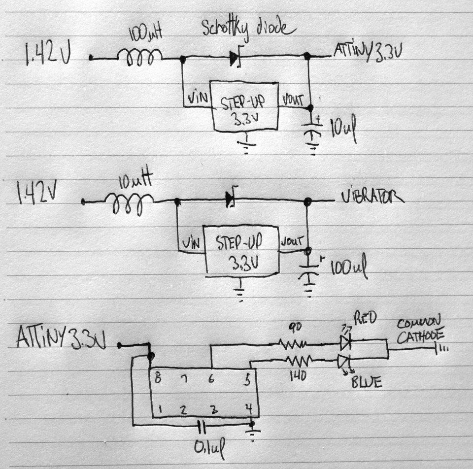
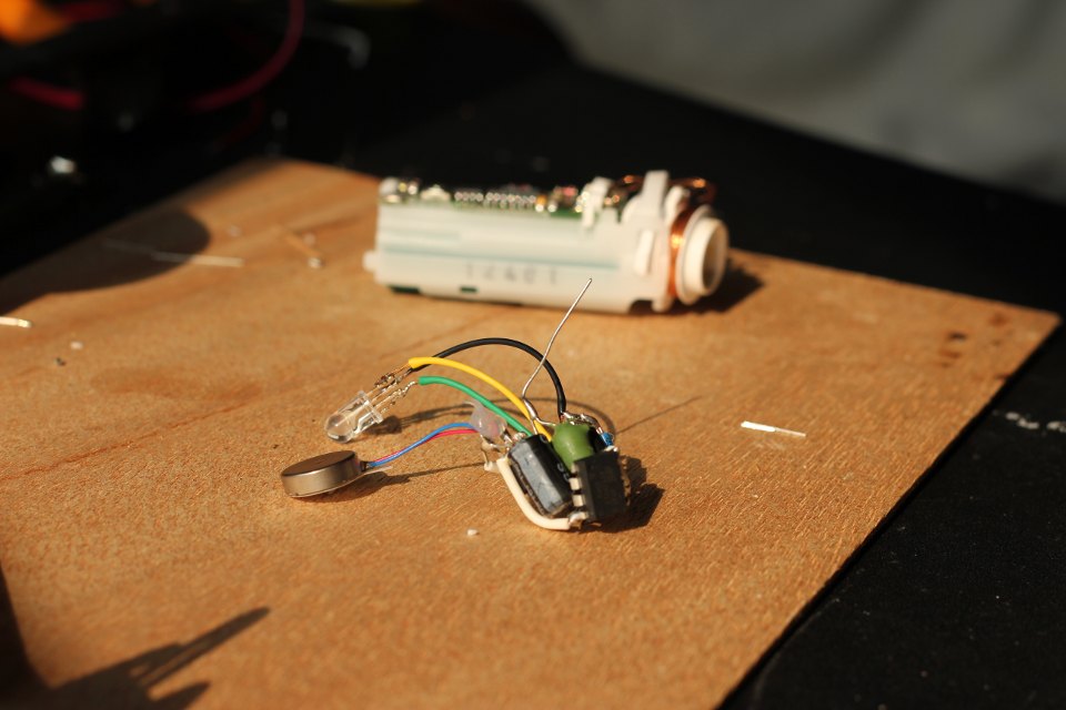
i am using polycaprolactone (FDA approuved). the schematic is pretty simple, but i had to play with the capacitor and inductor to get more power into the vibrator. it’s overkill to use an attiny for cycling the colors of the led (i didn’t know that you can buy RGB led with built-in pwm). even so, i am sharing the small code, maybe it can be useful to someone. since i am using an electric toothbrush there’s no physical connection to recharge it, thus completely waterproof. i will need to remelt the polycaprolactone to change the battery someday.
#define F_CPU 9600000UL #include <avr/io.h> #include <util/delay.h> #define LED PB0 #define LED2 PB1 int i; int main (void) { DDRB = 0xff; TCCR0A |= ((1 << COM0A1) | (1 << COM0A0) | (1 << COM0B1) | (1 << COM0B0) | (1 << WGM01) | (1 << WGM00)); // WGM01 - WGM00 (set fast PWM) OCR0A = 0; // initialize Output Compare Register A to 0 OCR0B = 0; TCCR0B |= (1 << CS01); // Start timer at Fcpu / 256 for (;;) { for (i = 0 ; i < 255 ; i++ ) // For loop (Up counter 0 - 255) { OCR0A = i; // Update Output Compare Register (PWM 0 - 255) _delay_ms(8); } for (i = 255 ; i > 1 ; i-- ) // For loop (down counter 255 - 0 ) { OCR0B = i; // Update Output Compare Register (PWM 0 - 255) _delay_ms(8); } for (i = 255 ; i > 1 ; i-- ) // For loop (down counter 255 - 0 ) { OCR0A = i; // Update Output Compare Register (PWM 0 - 255) _delay_ms(8); } for (i = 0 ; i < 255 ; i++ ) // For loop (Up counter 0 - 255) { OCR0B = i; // Update Output Compare Register (PWM 0 - 255) _delay_ms(8); } } } |
I lived in Shinjuku for a year, not too far from Akihabara. I met a friend at Tokyo Hacker Space who knows a lot about Akihabara; he was kind enough to allow me to film him doing a video tour. Keep in mind that many shops have closed since then:

I wrote this software (based on JMDict) to learn new words in japanese. It’s written in C++ (wxWidgets) and use sqlite3. A compiled version for Windows is available for download (with installer / uninstaller). I am sharing the source, but i won’t recommend to learn from it (a cobe::blocks project).
Here’s a screenshot in Windows:
Here’s a screenshot in Ubuntu / Gtk:

Download the installer (for Windows, beta)
Download the source (code::blocks)
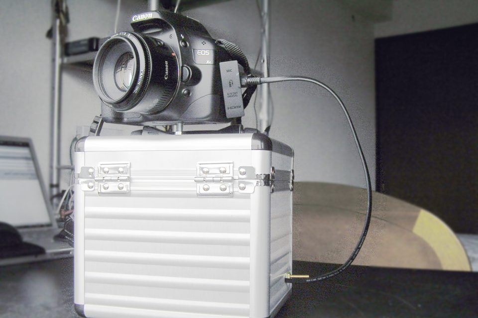
this project is obsolete if you own a Canon supported by http://wiki.magiclantern.fm
open source tool that runs from the SD/CF card at camera startup.
now that i have a digital camera (but my heart will always belong to film-based photography) i can do time lapse photography. sadly the firmware of my camera isn’t supporting this feature, so i had to build an intervalometer. i didn’t want to use an arduino (overkill & pricy), so i went with an attiny45, a generic optocoupler, a voltage regulator and a potentiometer for adjusting the timer from 1 second to 1 minute.
i just found out that it’s possible to power the avr from the camera (focus ring). have a look at this complete and small solution: http://www.doc-diy.net/photo/hdr-jack/
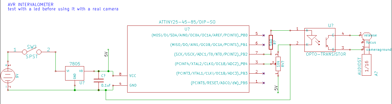
//Intervalometer from 1 second to 1 minute //Author: Patrick Sebastien Coulombe //Website: www.workinprogress.ca //Date: 2010-07-24 #define F_CPU 8000000 #include <avr/io.h> #include <util/delay.h> // use PB2 for led, pin 7 #define LED_BIT 2 // select ADC2, PB4, pin 3 #define CHANNEL 2 // shutter on (in ms) #define HOLD 300 // Return the 10bit value of the selected adc channel. uint16_t get_adc(uint8_t channel) { // ADC setup ADCSRA = (1 << ADEN) | (1 << ADPS1) | (1 << ADPS0); // select channel ADMUX = channel; // warm up the ADC, discard the first conversion ADCSRA |= (1 << ADSC); while (ADCSRA & (1 << ADSC)); ADCSRA |= (1 << ADSC); // start single conversion while (ADCSRA & (1 << ADSC)); // wait until conversion is done return ADCW; } // Scale long map(long x, long in_min, long in_max, long out_min, long out_max) { return (x - in_min) * (out_max - out_min) / (in_max - in_min) + out_min; } // Main program int main(void) { // vars uint16_t adcvalue = 0; uint16_t i; // define LED as outputs DDRB |= (1 << LED_BIT); while (1) { //release the shutter PORTB |= (1 << LED_BIT); //exposure length for (i=0; i<HOLD; i++) { _delay_ms(1); } PORTB &= ~(1 << LED_BIT); //interval time (using a potentiometer to adjust) adcvalue = map(get_adc(CHANNEL), 0, 1023, 1, 60); adcvalue = adcvalue * 1000; //one way to achieve long delay for (i=0; i<adcvalue; i++) { _delay_ms(1); } } return 0; } |
Time lapse test (3 hours) from my balcony.
I used Blender for making the tilt / shift effect. Here’s the source of the Blender file.
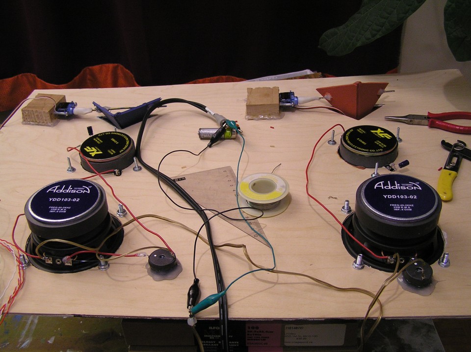
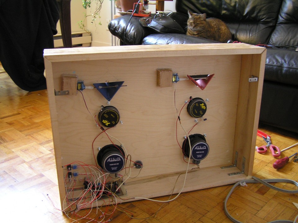
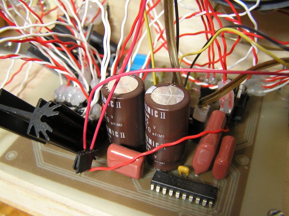
10 watts amplifier with built-in 16-bit / 48kHz RIFF-WAVE player (music on a SD-CARD). 2 servos for controlling the beaks. I did this project mostly to learn stuff. The result is a bit stupid.
VIDEO:
PHOTOS:

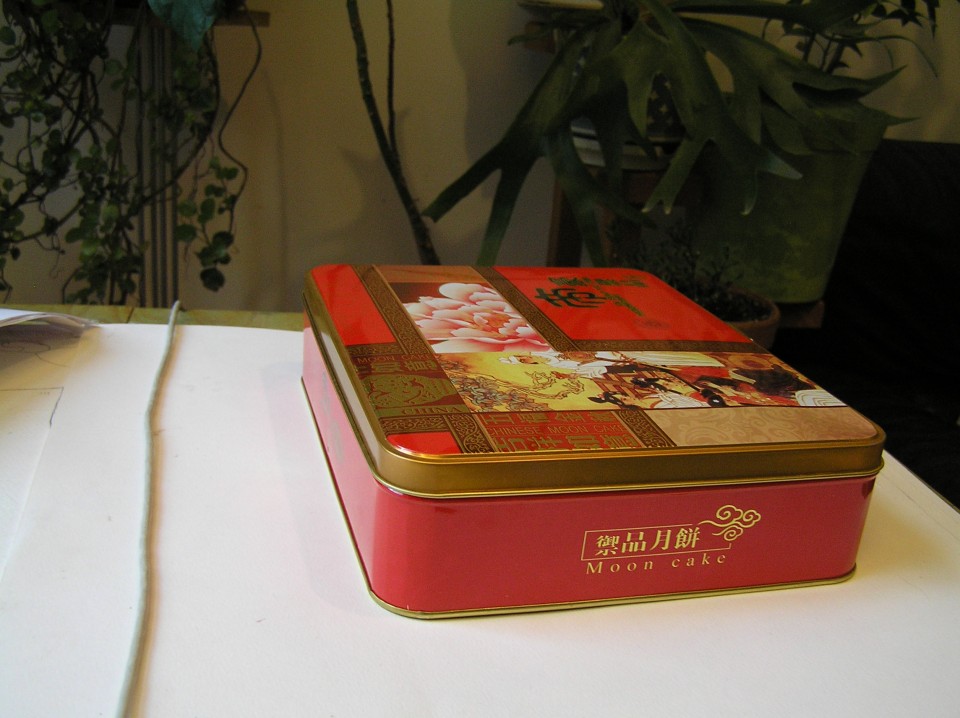
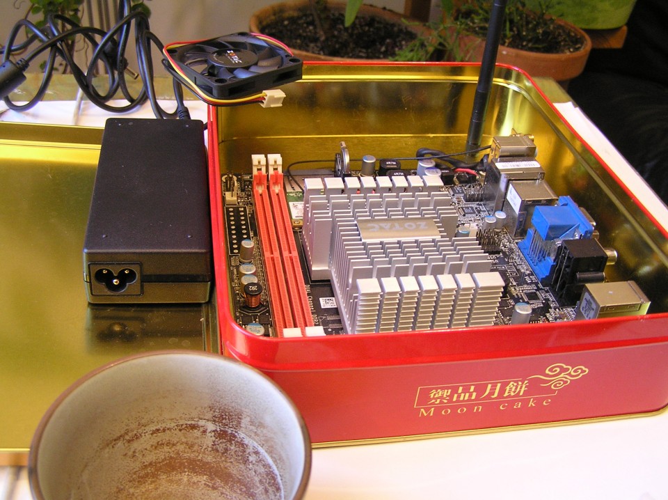
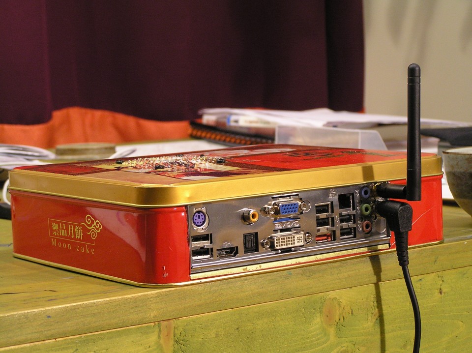
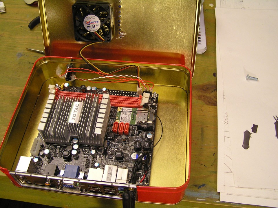
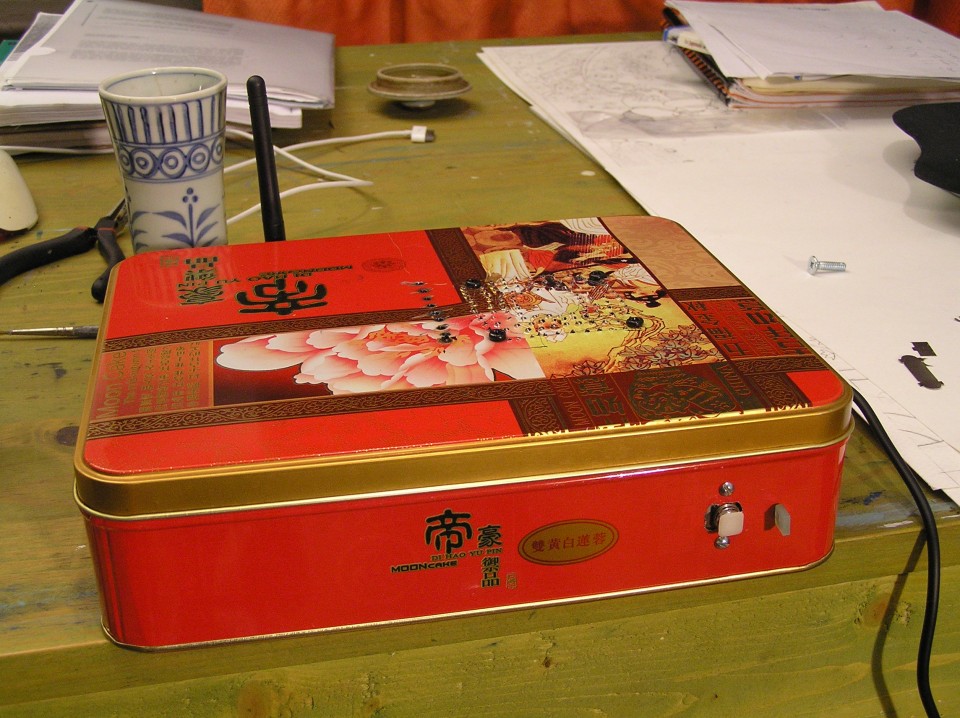
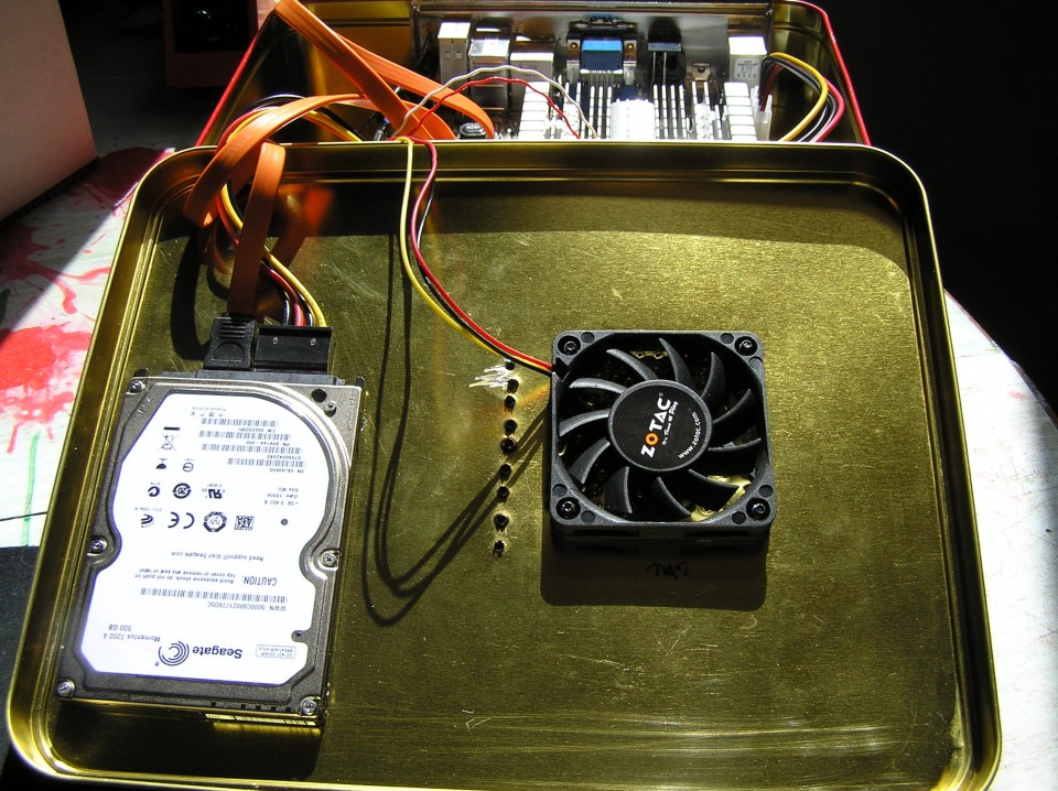
i am sure there’s plenty of projects like this one. the idea is to get a “cheap” and “small” full featured linux box. a good keyword to start with: itx motherboard cpu combo. this one have hdmi 1080p, wifi, dual-core 1.6 ghz. i paid 147$ used. got also 1 gig of used ram for 20$. total of 167$ CAD. weight is 0.8 kg for the box and 0.3 kg for the supply. Just 18W at idle, and 23W full load (someone measured it with a Kill-a-watt device). the power supply is 90W. for the storage, i went with a laptop hard-drive (it’s smaller). i paid 100$ for a 500 gig, 7200 rpm, sata.
all this information will be outdated, now.
running a realtime kernel with enlightenment and blender:
A very strange looking but tasty vegetarian curry.
Ingredients:
500g spinach
1 big onion
2-3 tomatoes
5 cloves of garlic
2cm of ginger
1 tbs cummin seed
1 tbs curcuma
1.5 tbs coriander powder
1 tbs galam masala
1/4 tbs cayen powder
3/4 tbs cream or yoghurt
1 tbs salt
150 g. paneer (indian cheese)
My favorite soup:
Tantan Nabe recipe
Ingredients for 4 people
1600ml chicken broth
20g zasai (finely chopped)
[A]
80g daikon (finely sliced)
80g carot (finely sliced)
80g egg plant (finely sliced)
4 leaves of hakusai (chinese cabbage)
4 shiitake mushroom
200g enoki mushroom
2tbs sake
5tbs soya sauce
some black pepper
1tbs rice vinegar
8tbs chi ma jan (芝麻醤) chinease sesame paste (or tahini)
2 green ognions
some chilli oil
[B] porc wonton (in the video i used tofu & fish cake)
100g ground porc
some black pepper
2tbs sake
1tbs soya sauce
some salt
some sugar
1tsp sesame oil
some corn starch
12 wonton wraps
How to cook:
1) Finely slice all [A] ingredient and put aside.
2) Put all [B] ingredients in a boul and mix well.
3) Bring chicken broth to boil in a big pot and add finely chopped zasai.
4) Wrap wonton as video shows below
5) Put all [A] ingredients into the pot and cook for 5 minutes at high heat.
6) In another pot, boil water and cook wonton for 2 minutes, then drain and put aside.
7) Add sake, soya sauce and black pepper into 5) and bring it to boil once.
8) Add vinegar
9) Add wonton
10) Add chi ma jan and mix gentely.
11) Add green ognion and chilli oil for your taste!
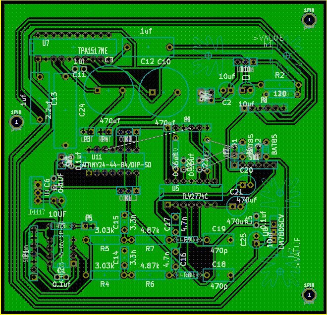
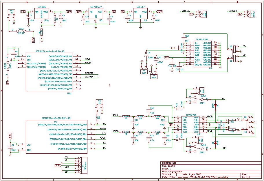
Kicad is an open source (GPL) software for the creation of electronic schematic diagrams and printed circuit board artwork.
schematic editor & cvpcb (transcript):
pcbnew (transcript):
V-USB kicad project (clean):
https://www.workinprogress.ca/wp-content/uploads/kicad_vusb.zip
Kicad:
http://kicad.sourceforge.net/wiki/index.php/Main_Page
Update:
http://kicad.1301.cz/
Libraries:
http://kicadlib.org/
http://per.launay.free.fr/kicad/kicad_php/composant.php
Tutorial:
http://KiCadHowTo.org
EEVblog review
i would like to start by saying that this solution might not be the best… if any analog guru read this, please leave a comment.
for 2.75$ you can have a chip that is able to run at 64 mhz (phase-locked loop) and output a pulse width modulation at 250 khz. attiny85 is your friend here. i didn’t found any atmega with this option (pll)… the good news is that it’s fast enough to output a stereo WAV at 16 bits / 48 khz. if you are interested in this project, take a look here: http://elm-chan.org/works/sd8p/report.html
since i want to connect the pwm output in a power amplifier, i need to filter the signal. here’s the waveform of the pulse width modulation @ 440 hz:

now let’s see if we use a simple RC low pass:

looks good to me, but then testing with a triangle instead of an oscillator revealed this:

that’s not beautiful… here’s a close-up:

maybe using more passive filter could help, but since you need to use an op-amp as a buffer (so that your load doesn’t affect the RC filter), why not use a sallen-key topology. this will act as an active low pass filter and a buffer. let’s look at the results:

close-up:

not perfect, but better!
SIMULATIONS
simple RC (250khz = -22db)

sallen-key second-order (250khz = -44db)

sallen-key third-order (250khz = -67db)

third-order is the best and using this method only 1 stage is needed.
when choosing the op-amp, consider this:
100 * highest Q * GBW = Gain Bandwidth Product (read about it here)
slew rate => 2V/µs
i am using a rail-to-rail input / output op-amp.
now simply add an electrolytic capacitor (100 uf) and you can feed an amplifier with the original pwm signal (hopefully).
Arduino use the FTDI chip for usb communication (not anymore). This chip is expensive and only surface mount. To save money and be able to make a PCB at home, i found a software-only implementation of USB for AVR (attiny, atmega): http://www.obdev.at/products/vusb/index.html.

You don’t need the 2 LEDs (visual feedback for debugging / bootloader).
Not using a bootloader? Then you can connect R4 to VCC (thus freeing PD4).

I am using an ATMEGA164p. The example code need to be modify to suit your device (bootloader address, registers, EEPROM functions).
This tutorial is for people who have some experience or are patient. Please pardon my english.
1) breadboard your avr for programmation (SPI / JTAG)
2) download vusb (last version)
A SIMPLE TEST (hid mouse)
cd vusb-x/examples/hid-mouse/firmware
open usbconfig.h – set the pin for usb (USB_CFG_DMINUS_BIT – USB_CFG_DPLUS_BIT)
open Makefile – edit DEVICE / F_CPU / FUSES / AVRDUDE
make hex
make program
Replug the device and automagically the mouse will move on your screen.
BOOTLOADERHID (optional)
3) download bootloadhid (last version)
This bootloader doesn’t require a driver (it’s HID). With it, you will be able to program your firmware without your programmer.
4) delete usbdrv, cp the usbdrv from vusb
5) open usbconfig.h – change the VENDOR and DEVICE name if you want
6) open bootloaderconfig.h – set the pin for usb (USB_CFG_DMINUS_BIT – USB_CFG_DPLUS_BIT) and if you want to be able to reset via usb (USB_CFG_PULLUP_IOPORTNAME). Change the bootloadcondition to suit your needs, i am using the EEPROM to write (from the firmware) & read (from the bootloader) + a button on PD5 (need to be hold) for the condition and finally 2 leds (so i know that i am in the bootloader).
7) main.c: Edit your condition, mine looks like this:
show code ▼
8) edit the Makefile
You need to know the BOOTLOADER_ADDRESS of your device (learn more about bootloader). Basically your datasheet will tell you the Start Bootloader section (look for Boot Size Configuration) in word address. You need to multiply it by 2 (the toolchain works on BYTE ADDRESS). For example, the atmega164p for 1024 words, the address is: 1C00 * 2 = 3800.
I am using a 20mhz clock, V-USB can be clocked with 12 Mhz, 15 MHz, 16 MHz or 20 MHz crystal or from a 12.8 MHz or 16.5 MHz internal RC oscillator.
Finally, you need to set the fuse correctly:
DEVICE = atmega164p
BOOTLOADER_ADDRESS = 3800
F_CPU = 20000000
FUSEH = 0xd8
FUSEL = 0xff
PROGRAMMER = avrispmkII
PORT = usb
...

make fuse
make flash
Now that you have the bootloaderhid, let's write a simple firmware to test it.
test.c
#define F_CPU 20000000 #include#include int main(void) { // Set Port B pins as all outputs DDRB = 0xff; while(1) { PORTB = 0xFF; _delay_ms(100); PORTB = 0x00; _delay_ms(200); } return 1; }
then:
avr-gcc -mmcu=atmega164p -Os test.c
avr-objcopy -j .text -j .data -O ihex a.out a.hex
cd bootloader/commandline
edit main.c if you changed the VENDOR and PRODUCT string
make
You need to connect the usb cable while holding the reset button. 2 LEDs should light up and you should see in dmesg something like:
[ 1727.956432] usb 3-2: new low speed USB device using uhci_hcd
[ 1728.119279] usb 3-2: configuration #1 chosen from 1 choice
[ 1728.142142] generic-usb 0003:16C0:05DF.000A: hiddev97,hidraw4: USB HID v1.01 Device [YOURVENDOR YOURPRODUCT] on usb-0000:00:1a.0-2/input0
Do:
./bootloadHID -r a.hex
FIRMWARE
Now what you want in your custom firmware is a way to tell your device to go in the bootloader (so you don't have to hold the reset button anymore). With this method in place, adding the reset button is optional, but recommanded (in case you break something in the firmware, you need a way to go back in the bootloader).
Remember, in the bootloader we are reading the EEPROM to see if we need to stay in the bootloader section, if not we load the firmware. So in the firmware we will write the EEPROM if we want to go in the bootloader.
show code ▼
You are ready to write the firmware for your application. Since you are using V-USB not only it let you upgrade your firmware very easily, but you can of course send and receive message between your computer and the device. Here's an example of sending the value of a potentiometer to your computer and telling your device to blink a led at a certain speed. This example is for my device, Atmega164p.
WINDOWS
You can trick Windows so it doesn't popup the driver installation when you plug your device. Your need to use a HID descriptor (Vendor type requests sent to custom HID class device).
hiddescriptor.h
show code ▼
usbconfig.h
show code ▼
Here's an example for installing the software & driver:
edubeat.zip
HOST SOFTWARE
Here's the most basic host software written in python.
show code ▼
HARDWARE
V-USB runs on any AVR microcontroller with at least 2 kB of Flash memory, 128 bytes RAM and a clock rate of at least 12 MHz. For example the ATTINY25 can do the job. The price of this chip is 1.66 2.00 USD!
TEMPLATE
Here's my template for the Atmega164p. This firmware is ready for ADC free-running mode, SPI master (you need to +5V PB4), external interrupts (PORTC), EEPROM read / write, jump to bootloader.
show code ▼
MIDI TEMPLATE
PUREDATA (custom-class) TEMPLATE
Communication from and to Pure Data
MORE INFORMATION
You can find more information about the API / USB Device Class / Host Software on the wiki of V-USB. Tutorial by Joonas Pihlajamaa: AVR ATtiny USB Tutorial.
Speech recognition done with Simon
Based on:
http://code.google.com/p/4bitsynth/
Atmega48 / pwm: square, triangle, noise.

Aphex Twin in 4 bits / 4 channels:
[dewplayer:https://www.workinprogress.ca/wp-content/uploads/4bitsaphex.mp3]
What is the difference between MIC and LINE level?
Level refers to the relative strength of the signal and is measured in decibels. LINE level sources are much-amplified signals over MIC (microphone) level signals. Line level is usually between -10 to +4 dbm in strength while MIC levels are normally -60 dbm.
Line OUT signal voltage and impedance levels?
The line output “standard” designed to drive a load of 600 ohms or greater, at a mean signal level of 0.775V RMS. An exception exists in respect of compact disc players, where the output level is most commonly 2V RMS.
Preamplifier schematic
Thanks to Andy Collinson for sharing his circuit design.

How does it sound?
Electret microphone
Sensitivity: -35 to +4dB
Signal to noise ratio: 62dB
Recorded at 96000 hertz @ 24 bits
emc_kalimba.wav (right click and save)
A simple bridge between glchess and pure data:
My first electronic project (2005):
since i don’t do PCB everyday…
it taste really good, no joke!
the purpose of this website is to share what i’ve learned mostly in technologies, but also in life. enjoy as is.