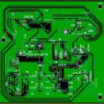
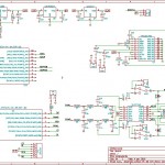
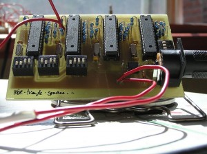
Arduino use the FTDI chip for usb communication (not anymore). This chip is expensive and only surface mount. To save money and be able to make a PCB at home, i found a software-only implementation of USB for AVR (attiny, atmega): http://www.obdev.at/products/vusb/index.html.
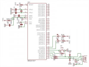
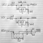
You don’t need the 2 LEDs (visual feedback for debugging / bootloader).
Not using a bootloader? Then you can connect R4 to VCC (thus freeing PD4).
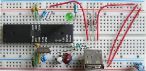
I am using an ATMEGA164p. The example code need to be modify to suit your device (bootloader address, registers, EEPROM functions).
This tutorial is for people who have some experience or are patient. Please pardon my english.
1) breadboard your avr for programmation (SPI / JTAG)
2) download vusb (last version)
A SIMPLE TEST (hid mouse)
cd vusb-x/examples/hid-mouse/firmware
open usbconfig.h – set the pin for usb (USB_CFG_DMINUS_BIT – USB_CFG_DPLUS_BIT)
open Makefile – edit DEVICE / F_CPU / FUSES / AVRDUDE
make hex
make program
Replug the device and automagically the mouse will move on your screen.
BOOTLOADERHID (optional)
3) download bootloadhid (last version)
This bootloader doesn’t require a driver (it’s HID). With it, you will be able to program your firmware without your programmer.
4) delete usbdrv, cp the usbdrv from vusb
5) open usbconfig.h – change the VENDOR and DEVICE name if you want
6) open bootloaderconfig.h – set the pin for usb (USB_CFG_DMINUS_BIT – USB_CFG_DPLUS_BIT) and if you want to be able to reset via usb (USB_CFG_PULLUP_IOPORTNAME). Change the bootloadcondition to suit your needs, i am using the EEPROM to write (from the firmware) & read (from the bootloader) + a button on PD5 (need to be hold) for the condition and finally 2 leds (so i know that i am in the bootloader).
show code ▼
#define JUMPER_BIT  5
#define BOOTLED_BIT  6
#define BOOTLED_BITB  7

static inline void  bootLoaderInit(void)
{
	DDRD |= (1 << BOOTLED_BIT);     // turn bootloader led on
	DDRD |= (1 << BOOTLED_BITB);     // turn bootloader led on 2
	PORTD |= (1 << JUMPER_BIT);     /* activate pull-up */
	_delay_us(10);  /* wait for levels to stabilize */
}

static inline void  bootLoaderExit(void)
{
    PORTD = (1 << BOOTLED_BIT);                 // turn bootloader led off
    PORTD = (1 << BOOTLED_BITB);                 // turn bootloader led off
}
7) main.c: Edit your condition, mine looks like this:
show code ▼
...
static void leaveBootloader()
{
 DBG1(0x01, 0, 0);
 bootLoaderExit();
 cli();
...
}
// ------------------------------------------------------------------------------
// - Write to EEPROM
// ------------------------------------------------------------------------------
void eepromWrite(unsigned int uiAddress, unsigned char ucData)
{
  /* Wait for completion of previous write */
  while(EECR & (1<
8) edit the Makefile
You need to know the BOOTLOADER_ADDRESS of your device (learn more about bootloader). Basically your datasheet will tell you the Start Bootloader section (look for Boot Size Configuration) in word address. You need to multiply it by 2 (the toolchain works on BYTE ADDRESS). For example, the atmega164p for 1024 words, the address is: 1C00 * 2 = 3800.
I am using a 20mhz clock, V-USB can be clocked with 12 Mhz, 15 MHz, 16 MHz or 20 MHz crystal or from a 12.8 MHz or 16.5 MHz internal RC oscillator.
Finally, you need to set the fuse correctly:
- Boot Flash section size = 1024 words
- Uncheck Divide clock by 8 internally
DEVICE = atmega164p
BOOTLOADER_ADDRESS = 3800
F_CPU = 20000000
FUSEH = 0xd8
FUSEL = 0xff
PROGRAMMER = avrispmkII
PORT = usb
...

make fuse
make flash
Now that you have the bootloaderhid, let's write a simple firmware to test it.
test.c
#define F_CPU 20000000
#include
#include

int main(void) {

	// Set Port B pins as all outputs
	DDRB = 0xff;

  while(1) {

    PORTB = 0xFF;
    _delay_ms(100);

    PORTB = 0x00;
    _delay_ms(200);

  }

  return 1;
}
then:
avr-gcc -mmcu=atmega164p -Os test.c
avr-objcopy -j .text -j .data -O ihex a.out a.hex
cd bootloader/commandline
edit main.c if you changed the VENDOR and PRODUCT string
make
You need to connect the usb cable while holding the reset button. 2 LEDs should light up and you should see in dmesg something like:
[ 1727.956432] usb 3-2: new low speed USB device using uhci_hcd
[ 1728.119279] usb 3-2: configuration #1 chosen from 1 choice
[ 1728.142142] generic-usb 0003:16C0:05DF.000A: hiddev97,hidraw4: USB HID v1.01 Device [YOURVENDOR YOURPRODUCT] on usb-0000:00:1a.0-2/input0
Do:
./bootloadHID -r a.hex
FIRMWARE
Now what you want in your custom firmware is a way to tell your device to go in the bootloader (so you don't have to hold the reset button anymore). With this method in place, adding the reset button is optional, but recommanded (in case you break something in the firmware, you need a way to go back in the bootloader).
Remember, in the bootloader we are reading the EEPROM to see if we need to stay in the bootloader section, if not we load the firmware. So in the firmware we will write the EEPROM if we want to go in the bootloader.
show code ▼
// ------------------------------------------------------------------------------
// - Write to EEPROM
// ------------------------------------------------------------------------------
void eepromWrite(unsigned int uiAddress, unsigned char ucData) {
  while(EECR & (1<
You are ready to write the firmware for your application. Since you are using V-USB not only it let you upgrade your firmware very easily, but you can of course send and receive message between your computer and the device. Here's an example of sending the value of a potentiometer to your computer and telling your device to blink a led at a certain speed. This example is for my device, Atmega164p.
vusbtut.tar.gz
WINDOWS
You can trick Windows so it doesn't popup the driver installation when you plug your device. Your need to use a HID descriptor (Vendor type requests sent to custom HID class device).
hiddescriptor.h
show code ▼
// This HidReportDescriptor is not used, it's only here for avoiding a driver popup install on Windows
// See: Vendor type requests sent to custom HID class device
// http://vusb.wikidot.com/usb-device-classes

PROGMEM char usbHidReportDescriptor[33] = {
0x06, 0x00, 0xff,              // USAGE_PAGE (Generic Desktop)
0x09, 0x01,                    // USAGE (Vendor Usage 1)
0xa1, 0x01,                    // COLLECTION (Application)
0x15, 0x00,                    //   LOGICAL_MINIMUM (0)
0x26, 0xff, 0x00,              //   LOGICAL_MAXIMUM (255)
0x75, 0x08,                    //   REPORT_SIZE (8)

0x85, 0x01,                    //   REPORT_ID (1)
0x95, 0x06,                    //   REPORT_COUNT (6)
0x09, 0x00,                    //   USAGE (Undefined)
0xb2, 0x02, 0x01,              //   FEATURE (Data,Var,Abs,Buf)

0x85, 0x02,                    //   REPORT_ID (2)
0x95, 0x83,                    //   REPORT_COUNT (131)
0x09, 0x00,                    //   USAGE (Undefined)
0xb2, 0x02, 0x01,              //   FEATURE (Data,Var,Abs,Buf)
0xc0                           // END_COLLECTION
};
usbconfig.h
show code ▼
#define USB_CFG_DEVICE_CLASS        0    /* set to 0 if deferred to interface */
#define USB_CFG_DEVICE_SUBCLASS     0
/* See USB specification if you want to conform to an existing device class.
* Class 0xff is "vendor specific".
*/
#define USB_CFG_INTERFACE_CLASS     0x03   /* define class here if not at device level */
#define USB_CFG_INTERFACE_SUBCLASS  0
#define USB_CFG_INTERFACE_PROTOCOL  0
/* See USB specification if you want to conform to an existing device class or
* protocol. The following classes must be set at interface level:
* HID class is 3, no subclass and protocol required (but may be useful!)
* CDC class is 2, use subclass 2 and protocol 1 for ACM
*/
#define USB_CFG_HID_REPORT_DESCRIPTOR_LENGTH    33
main.c
#include
#include
#include
#include
#include "usbdrv.h"
#include "hiddescriptor.h"
Here's an example for installing the software & driver:
edubeat.zip
HOST SOFTWARE
Here's the most basic host software written in python.
show code ▼
import usb

def findDevice(vendor_id):
	buses = usb.busses()
	for bus in buses :
		for device in bus.devices :
			print 'idVendor: %x' % device.idVendor
			if device.idVendor == vendor_id:
				print 'Found'
				return device
	return None

class VUSB:
	USB_VENDOR_ID = 0x16C0
	REQUEST_TYPE = usb.TYPE_VENDOR | usb.RECIP_DEVICE | usb.ENDPOINT_IN

	USB_BUFFER_SIZE = 2
	CMD_ZERO = 0

	def __init__(self):
		device = findDevice(self.USB_VENDOR_ID)
		if not device:
			raise Exception('Device not available')
		self.handle = device.open()

	def getBufferSize(self):
		return self.send_cmd(self.CMD_ZERO)

	def send_cmd(self, cmd, param=0):
		val = self.handle.controlMsg(requestType = self.REQUEST_TYPE, request = cmd, value = param, buffer = self.USB_BUFFER_SIZE)
		return val

def main():
	client = VUSB()
	print client.getBufferSize()

if __name__ == '__main__':
	main()
HARDWARE
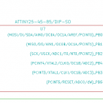
V-USB runs on any AVR microcontroller with at least 2 kB of Flash memory, 128 bytes RAM and a clock rate of at least 12 MHz. For example the ATTINY25 can do the job. The price of this chip is 1.66 2.00 USD!
TEMPLATE
Here's my template for the Atmega164p. This firmware is ready for ADC free-running mode, SPI master (you need to +5V PB4), external interrupts (PORTC), EEPROM read / write, jump to bootloader.
show code ▼
#include
#include
#include
#include
#include

#include "usbdrv.h"
#include "hiddescriptor.h"
#include "utils.h"

// - Define
#define DD_MOSI     PINB5
#define DD_SCK      PINB7
#define ADC_PINS 8

// - Global
static uint8_t usb_reply[10];

// - Write to EEPROM
void eepromWrite(unsigned int uiAddress, unsigned char ucData) {
	while(EECR & (1<bRequest == 0) { //POST

		replyBuf[0] = usb_reply[0];
		replyBuf[1] = usb_reply[1];
		replyBuf[2] = usb_reply[2];
		replyBuf[3] = usb_reply[3];
		replyBuf[4] = usb_reply[4];
		replyBuf[5] = usb_reply[5];
		replyBuf[6] = usb_reply[6];
		replyBuf[7] = usb_reply[7];
		replyBuf[8] = usb_reply[8];
		replyBuf[9] = usb_reply[9];
		return 10;

	} else if(rq->bRequest == 1) { //GET
		//rq->wIndex.bytes[0];
		//rq->wValue.bytes[0];
	}
	return 0;
}

// - InterruptInit
void InterruptInit() {
	PCICR |= (1 << PCIE2);
	PCMSK2 |= (1 << PCINT23) | (1 << PCINT22) | (1 << PCINT21) | (1 << PCINT20) | (1 << PCINT19) | (1 << PCINT18) | (1 << PCINT17) | (1 << PCINT16);
}

// - InterruptTrigged
SIGNAL (SIG_PIN_CHANGE2)
{
	//CODE
}

// - SPI_MasterInit
void SPI_MasterInit(void) {
	/* Set MOSI and SCK output, all others input */
	DDRB = (1< USB reset) */
	#ifdef USB_CFG_PULLUP_IOPORT    /* use usbDeviceConnect()/usbDeviceDisconnect() if available */
		USBDDR = 0;        /* we do RESET by deactivating pullup */
		usbDeviceDisconnect();
	#else
		USBDDR = (1 << USB_CFG_DMINUS_BIT) | (1 << USB_CFG_DPLUS_BIT);
	#endif

	j = 0;
	while (--j) {        /* USB Reset by device only required on Watchdog Reset */
		i = 0;
		while (--i);    /* delay >10ms for USB reset */
	}

	#ifdef USB_CFG_PULLUP_IOPORT
		usbDeviceConnect();
	#else
		USBDDR = 0;        /*  remove USB reset condition */
	#endif

	// ADC SETUP :: FREE RUNNING MODE

	// PRESCALER 64
	ADCSRA |= (1 << ADPS2) | (1 << ADPS1) | (0 << ADPS0);
	// AUTO TRIGGER ENABLE
	ADCSRA |= (1 << ADATE);
	// AVCC with external capacitor at AREF pin
	ADMUX |= (0 << REFS1) | (1 << REFS0);
	// RIGHT ADJUST
	ADMUX |= (0 << ADLAR);
	// CHANNEL 0
	ADMUX |= (0 << MUX4) | (0 << MUX3) | (0 << MUX2) | (0 << MUX1) | (0 << MUX0);
	// FREE RUNNING MODE
	ADCSRB |= (0 << ADTS2) | (0 << ADTS1) | (0 << ADTS0);
	// ENABLE ADC
	ADCSRA |= (1 << ADEN);

	// PORT A: INPUT
	DDRA = 0x00;
	PORTA = 0x00;

	// PORT B: OUTPUT
	DDRB = 0xFF;

	// PORT C: INPUT
	DDRC = 0x00;

	//POWER LED
	DDRD |= (1 << 6);
	PORTD &= ~(1 << 6);

	//SPI init
	SPI_MasterInit();

	//Interrupt init
	InterruptInit();
}

// - Main
int main(void) {
	wdt_enable(WDTO_1S);
	hardwareInit();
	usbInit();
	sei();

	ADCSRA |= (1 << ADSC); //Start Free Running Mode

	while(1) {
		wdt_reset();
		usbPoll();

		//BOOTLOADER
		if(bit_is_clear(PIND, 5)) {
		startBootloader();
		}

		//SPI CODE
		SPI_MasterTransmit('A');

		//YOUR CODE

		//USB TEST
		usb_reply[0] = 1;
		usb_reply[1] = 2;
		usb_reply[2] = 3;
		usb_reply[3] = 4;
		usb_reply[4] = 5;
		usb_reply[5] = 6;
		usb_reply[6] = 7;
		usb_reply[7] = 8;
		usb_reply[8] = 0;
		usb_reply[9] = 0;
	}
	return 0;
}
MIDI TEMPLATE
For USB MIDI IN/OUT
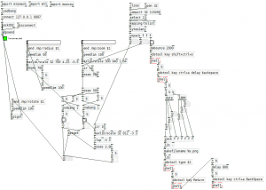
PUREDATA (custom-class) TEMPLATE
Communication from and to Pure Data
MORE INFORMATION
You can find more information about the API / USB Device Class / Host Software on the wiki of V-USB. Tutorial by Joonas Pihlajamaa: AVR ATtiny USB Tutorial.
