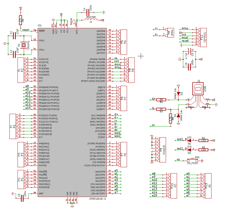
Source
Introduction | Source
https://github.com/patricksebastien/hicu

BOM
|
Description |
Digi-Key Part Number |
Quantity |
|
|
RES TF 68 OHM 1% 0.25W 1206 |
RMCF1206FT68R0CT-ND |
2 |
|
|
RES 1.5K OHM 1/4W 1% 1206 SMD |
RMCF1206FT1K50CT-ND |
1 |
|
|
RES 47.0K OHM 1/4W 1% 1206 SMD |
P47.0KFCT-ND |
1 |
|
|
RES 150 OHM 1/4W 1% 1206 SMD |
RMCF1206FT150RCT-ND |
2 |
|
|
LED GREEN CLEAR 1206 SMD |
160-1169-1-ND |
1 |
|
|
LED RED ORANGE CLEAR 1206 SMD |
160-1168-1-ND |
1 |
|
|
CAP CER 0.1UF 50V 10% X7R 1206 |
399-1249-1-ND |
3 |
|
|
CRYSTAL 16.000 MHZ 18PF SMD |
887-1086-1-ND |
1 |
|
|
CONN HEADER 6POS .100 STR TIN |
609-3218-ND |
1 |
|
|
IC MCU AVR 64K FLASH 100-TQFP |
ATMEGA640-16AU-ND |
1 |
|
|
CAP CER 18PF 50V 5% NPO 1206 |
311-1152-1-ND |
2 |
|
|
DIODE ZENER 3.6V 500MW DO-35 |
1N5227BDICT-ND |
2 |
|
|
CHOKE CONFORMAL COATED 10UH |
M10135-ND |
1 |
|
|
SWITCH TACTILE SPST-NO 0.05A 24V |
JB15KP-ND |
1 |
|
+ USB; 4.7uf CAP & HEADERS = +- 20$ CAD + 2$ for the PCB
https://www.digikey.ca/classic/RegisteredUser/BOMBillOfMaterials.aspx?path=1&exist=1&id=353568
LINUX udev permission for HiCu
/lib/udev/rules.d/99-avrisp.rules
SUBSYSTEM==”usb”, ATTRS{idProduct}==”05dc”, ATTRS{idVendor}==”16c0″, MODE=”0666″
or
SUBSYSTEM!=”usb_device”, ACTION!=”add”, GOTO=”avrisp_end”
ATTR{idVendor}==”16c0″, ATTR{idProduct}==”05dc”, MODE=”666″, GROUP=”audio”
LABEL=”avrisp_end”
on the raspberry pi, change /lib/udev/rules.d/91-permissions.rules
SUBSYSTEM==”usb”, ENV{DEVTYPE}==”usb_device”, \
MODE=”0666″
Makefile
## General Flags PROJECT = xxx MCU = atmega640 TARGET = $(PROJECT).elf CC = avr-gcc AVRDUDE = avrdude -P usb -c avrispmkII -p$(MCU) ## Options common to compile, link and assembly rules COMMON = -g -mmcu=$(MCU) ## Compile options common for all C compilation units. CFLAGS = $(COMMON) CFLAGS += -Wall -DF_CPU=16000000UL -Os -fsigned-char ## Assembly specific flags ASMFLAGS = $(COMMON) ASMFLAGS += -x assembler-with-cpp -Wa, ## Linker flags LDFLAGS = $(COMMON) LDFLAGS += -Wl,-Map=$(PROJECT).map ## Intel Hex file production flags HEX_FLASH_FLAGS = -R .eeprom ## Include Directories INCLUDES = -I"." -I"../usbdrv" -I"../." ## Objects that must be built in order to link OBJECTS = usbdrv.o usbdrvasm.o oddebug.o main.o ## Objects explicitly added by the user LINKONLYOBJECTS = ## Build all: $(TARGET) $(PROJECT).hex $(PROJECT).lss $(OBJECTS): usbconfig.h Makefile ## Compile usbdrv.o: ../usbdrv/usbdrv.c $(CC) $(INCLUDES) $(CFLAGS) -c $< usbdrvasm.o: ../usbdrv/usbdrvasm.S $(CC) $(INCLUDES) $(ASMFLAGS) -c $< oddebug.o: ../usbdrv/oddebug.c $(CC) $(INCLUDES) $(CFLAGS) -c $< main.o: main.c $(CC) $(INCLUDES) $(CFLAGS) -c $< ##Link $(TARGET): $(OBJECTS) $(CC) $(LDFLAGS) $(OBJECTS) $(LINKONLYOBJECTS) $(LIBDIRS) $(LIBS) -o $(TARGET) %.hex: $(TARGET) avr-objcopy -O ihex $(HEX_FLASH_FLAGS) $< $@ %.lss: $(TARGET) avr-objdump -h -S $< > $@ ## Clean target .PHONY: clean clean: -rm -rf $(OBJECTS) $(PROJECT).* *~ .PHONY: flash flash: all $(AVRDUDE) -U flash:w:$(PROJECT).hex |
usbconfig.h
#define F_CPU 16000000UL /* ---------------------------- Hardware Config ---------------------------- */ #define USB_CFG_IOPORTNAME D /* This is the port where the USB bus is connected. When you configure it to * "B", the registers PORTB, PINB and DDRB will be used. */ #define USB_CFG_DMINUS_BIT 1 /* This is the bit number in USB_CFG_IOPORT where the USB D- line is connected. * This may be any bit in the port. */ #define USB_CFG_DPLUS_BIT 0 /* This is the bit number in USB_CFG_IOPORT where the USB D+ line is connected. * This may be any bit in the port. Please note that D+ must also be connected * to interrupt pin INT0! */ /* ----------------------- Optional Hardware Config ------------------------ */ #define USB_CFG_PULLUP_IOPORTNAME D /* If you connect the 1.5k pullup resistor from D- to a port pin instead of * V+, you can connect and disconnect the device from firmware by calling * the macros usbDeviceConnect() and usbDeviceDisconnect() (see usbdrv.h). * This constant defines the port on which the pullup resistor is connected. */ #define USB_CFG_PULLUP_BIT 4 /* This constant defines the bit number in USB_CFG_PULLUP_IOPORT (defined * above) where the 1.5k pullup resistor is connected. See description * above for details. */ /* #define USB_BUFFER_SECTION ".bss" */ /* The USB receive buffer (variable "usbRxBuf") with a length of 22 bytes * MUST NOT cross a 256 byte boundary. We have introduced this configuration * option to allow you to change the data segment where this buffer is * allocated. If you have problems with the default segment (start of .bss), * you may change this setting. See the comment in usbdrv.h for details. * On IAR C, the default is the TINY_Z segment (first 256 bytes). You must * change this default for devices which don't have RAM below 0x100. */ |
Bootloader address:
0x7000 (*2 (E000) for V-USB BootloaderHID)
Fuses:
FUSE_L = 0xff
FUSE_H = 0xd8